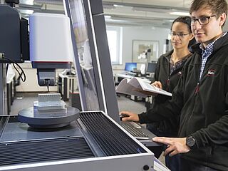
High-quality metrology for quality control in the measuring room, production, incoming goods and development.
Gear Metering Pumps & Meter Mix Dispense Machines with highest accuracy for processing liquids and pastes.
High-precision rotary stroke bearings for backlash-free linear and rotational movements for use in machine and device construction.


Innovative handheld measuring equipment from Mahr: Calipers, micrometers and dial indicators from analog to digital models with integrated wireless transmission. Mahr's comparative measuring instruments and reference standards are indispensable for your precise production metrology.
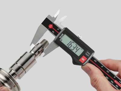
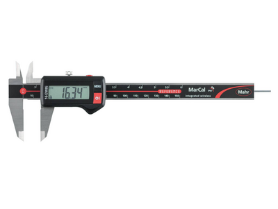
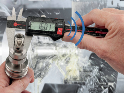
From analog to digital, the entire spectrum of calipers. Easy handling, wireless, and highly accurate. Perfect for efficient use in manufacturing.
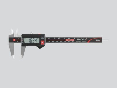
A safe, easy to read digital display, the modern design and the usual Mahr accuracy characterize our digital calipers. The range includes measuring instruments for all applications. Various interfaces for data transmission and protection rating up to IP 67 leave no demands unfulfilled.
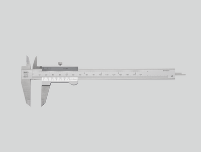
Glare-free reading, hardened steel, raised guideways to protect the scale and provide the highest accuracy. Features of a quality caliper from Mahr with the classic vernier caliper.
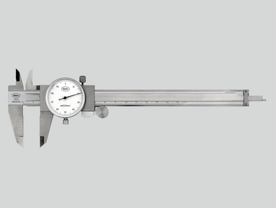
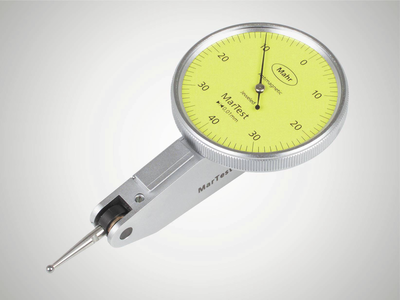
Large, high-contrast dial and shock-protected measuring tool for lasting precision. A tried and tested mechanical design for fast and safe reading.
Maximum precision in a variety of designs. Micrometers from Mahr are available in conventional mechanical and digital and wireless versions.
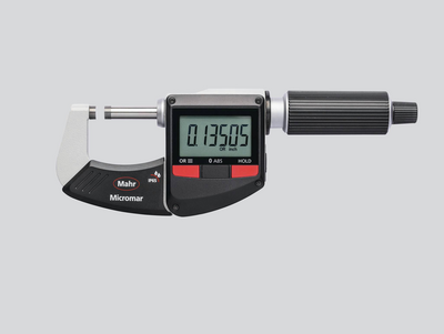
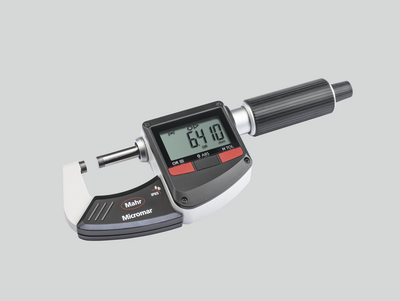
A clear digital display, modern design and the usual Mahr accuracy characterize our digital outside micrometers. The range includes measuring instruments for all applications. Various interfaces for data transmission and a high protection rating up to IP 65 leave no demands unfulfilled.
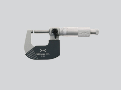
Anti-glare reading, thermal insulation plates and a precision-ground spindle for maximum accuracy. Features of a quality micrometer from Mahr.
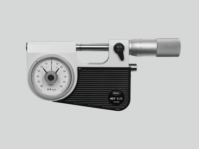
Particularly suitable for reliable and fast testing of series parts (shafts, bolts, shanks). The dimensional accuracy is recognized and read at a glance on the dial comparator.
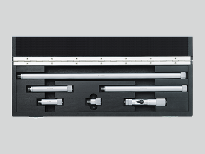
Suitable for measuring large diameters and testing distances up to 2,500 mm
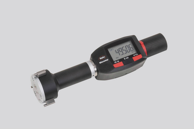
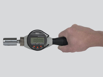
Available with scale or digital display or as a quick-measuring instrument with pistol-type grip. The Mahr 3-point inner measuring devices always provide reliable measuring results due to automatic self-centering.
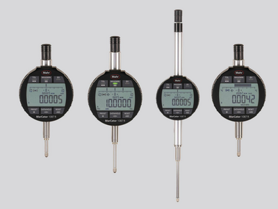
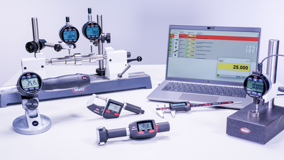
From analog to digital, the entire spectrum of dial gages, dial comparators and dial test indicators. Easy handling, wireless (optionally), and highly accurate. Perfect for efficient use in manufacturing.
A clear digital display, robust construction and high Mahr accuracy characterize our digital dial gages. The range includes measuring instruments for all applications. Various interfaces for data transfer and a high protection rating up to IP 54 leave no demands unfulfilled.
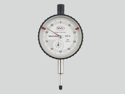
High sensitivity and accuracy due to: Solid mounting of the measuring tool axes, precision-geared wheels and pinions, high-precision mounted measuring pin.
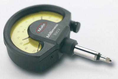
Compared to analog dial indicators, Millimess dial comparators have even more precise components, providing better measuring accuracy and a much improved hysteresis error. These advantages are particularly evident in runout tests, straightness and flatness measurements and comparative measurements.
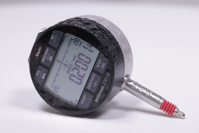
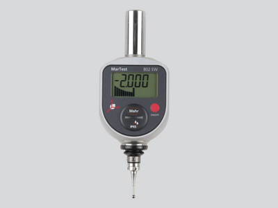
The high-precision inductive Millimess dial comparators are capable of digital increments of up to 0.2 μm. User-friendly operating functions such as tolerance monitoring, minimum or maximum recording for dynamic measurements, a combined numerical and scale display and simple data transfer make it an indispensable precision measuring instrument.
The sensitive computer-optimised measuring tool ensures maximum reliability and precision. For rough workshop use, the display is superbly protected against scratching or breakage by a hardened mineral glass pane, and a seal also provides reliable protection against penetrating liquids.
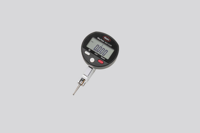
The sensitive computer-optimised measuring tool ensures maximum reliability and precision. For rough workshop use, the display is superbly protected. A seal also provides reliable protection against penetrating liquids.
Mahr 3D measuring probes for NC machines, machining centers and eroding machines shorten setup and downtimes. Perfect for accurately contacting reference edges on workpieces and fixtures.
Whether Integrated Wireless, external wireless modules, USB, Opto RS232, or Digimatic: Regardless of which interface standard you use, MarConnect will always provide the best connection.
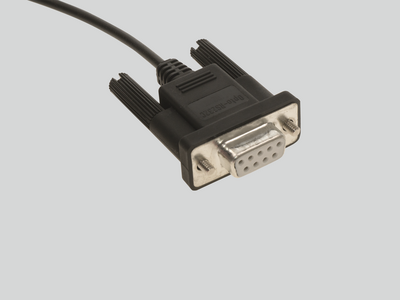
Many Mahr precision gages have a data output with MarConnect interface. Regardless of which interface standard you use, (USB, Opto RS232 or Digimatic), MarConnect will always provide the best connection.
Mahr’s Wireless range guarantees you precise measuring results with full mobility. The modern and easy way to measure – without the restrictions of wired technology.
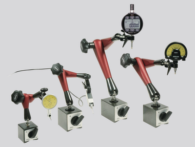
MarStand measuring tripods, measuring tables and radial run-out gages offer high stability, the basis for precise measuring results. They offer the necessary support for your dial indicators, dial comparators, dial test indicator measuring devices and measuring probes.
Measuring tripods provide the basis for precise measuring results due to their stable design. They offer the necessary support for your dial indicators, dial comparators, dial test indicator measuring devices and measuring probes.
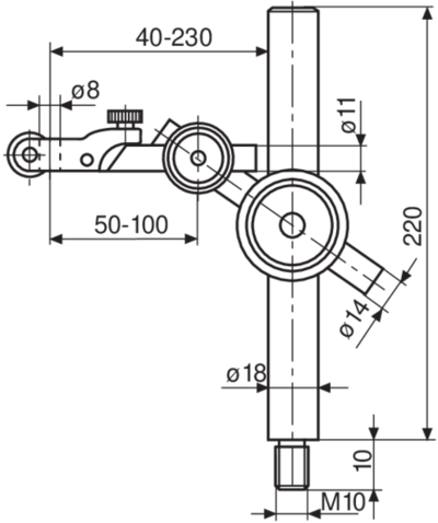
MarStand post and support assemblies are used for individual solutions and offer high stability, the basis for precise measuring results. They offer the necessary support for dial indicators, dial comparators, dial test indicator measuring devices and measuring probes.
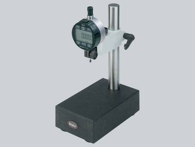
Measuring tables combine a precise and level measuring table, a stable measuring column and strong arm parts. MarStand measuring tables provide the basis for precise measuring results due to their extra stable design.
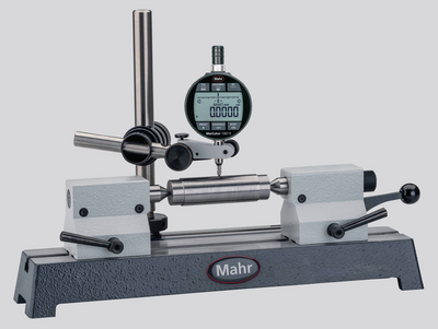
Radial run-out gages are the simplest method of detecting positional and form errors on shafts in a close-to-production environment. Due to the variety of models, the robust MarStand radial run-out gages form the basis for a wide range of workpiece requirements and precise measuring results.
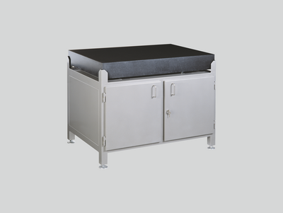
Test plates made of hard granite are the perfect surface for your height measurement instruments due to the plates’ high strength and dimensional stability.
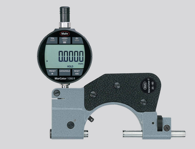
Using indicating gages as comparative gages make the perfect tool for precision measurements in manufacturing. Setting the gage to a reference standard reduces the deviation margin and minimizes the influence of temperature fluctuations on the measurement result.
Indicating snap gages are the perfect measuring tools for precision measurements of cylindrical parts such as shafts, bolts and shanks, especially for safe and fast tests on series parts. The dimensional accuracy is identified and read at a glance on the dial comparator.
Inner measuring devices are the perfect tools for precisely measuring the diameter, roundness and conicity of holes.
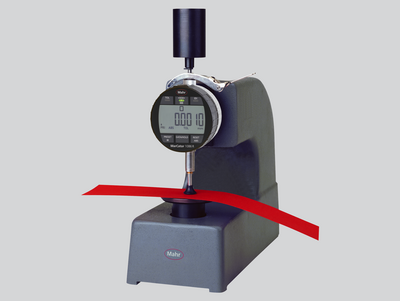
Our thickness gages offer a robust and simple range for particularly fast measurement of a variety of films, sheets, and plates.
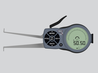
If common measuring instruments such as calipers or inner micrometer screws cannot be used due to the workpiece geometry, caliper gages are the perfect solution!
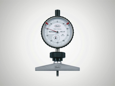
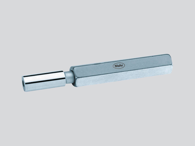
Our depth gages offer a robust and simple range for particularly fast depth measurements. The 8mm mounting shaft allows the use of dial indicators, dial comparators and probes according to the measuring task.
Universal measuring instruments are the perfect partners for precision measurements in production, because the comparison measurement to a reference standard minimizes the influence of temperature fluctuations on the measurement result.
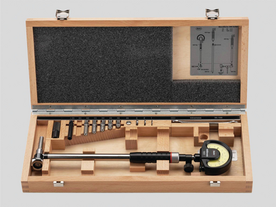
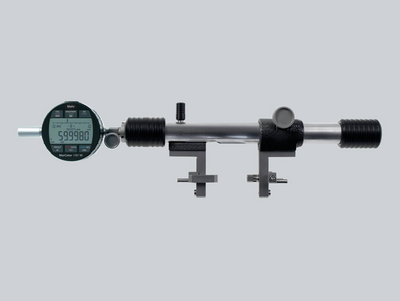
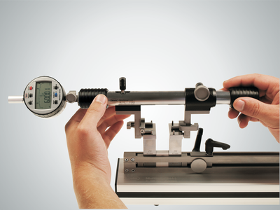
No matter whether gear, thread, taper or recess: Multimar universal measuring instruments are an ideal solution for almost all internal and external measurements for which standard measuring instruments are not suitable. A choice of basic units and an extensive range of accessories are available.
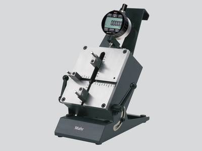
Accurately adjust your inside and outside measuring instruments. When using the 844 S setting instruments, you are perfectly equipped for every measuring task - even for larger dimensions.
No matter whether centering shoulders, narrow collars or recesses: The Multimar 36B universal measuring instruments are an ideal solution for almost all inner and outer measurements. A choice of basic units and an extensive range of accessories are available.
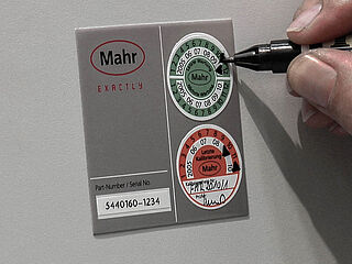
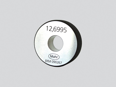
Trust in Mahr setting standards and gages – because they are the basis for precise measuring results.
Trust in Mahr’s setting standards - because they are the basis for precise measuring results.
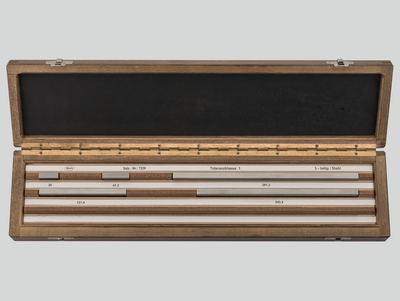
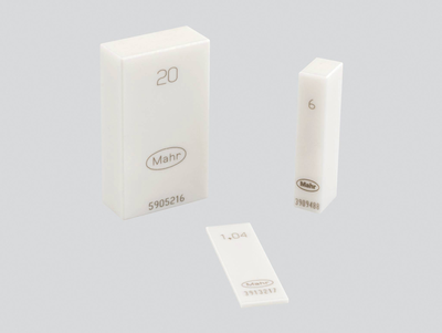
Mahr gage blocks ensure that you have high-quality reference and working standards at your disposal. Choose from four tolerance classes and two materials to suit the requirements of your workshop, production or quality assurance.
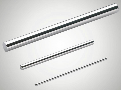
Mahr pin gages are available in three tolerance classes and various designs. Choose the device to suit the requirements of your workshop, production or quality assurance.
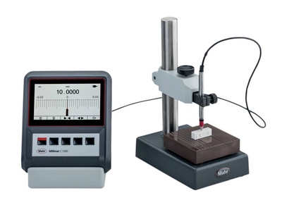
The requirements for electrical length measuring instruments are just as varied as their applications. Excellent reliability, precision and simple operation are called for.
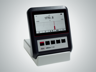
The requirements for electrical length measuring instruments are just as varied as their applications. Excellent reliability, precision and simple operation are called for. Millimar compact and column measuring instruments meet these requirements.
Millimar length measuring instruments are compact, robust, and easy to use. They are versatile evaluation and indicating instruments for measuring tasks of manageable complexity in the production area and in the measuring room.
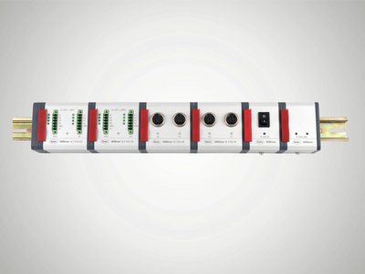
The diverse combination options of modules and software provide the opportunity to design a working environment and tools more individually than ever before.
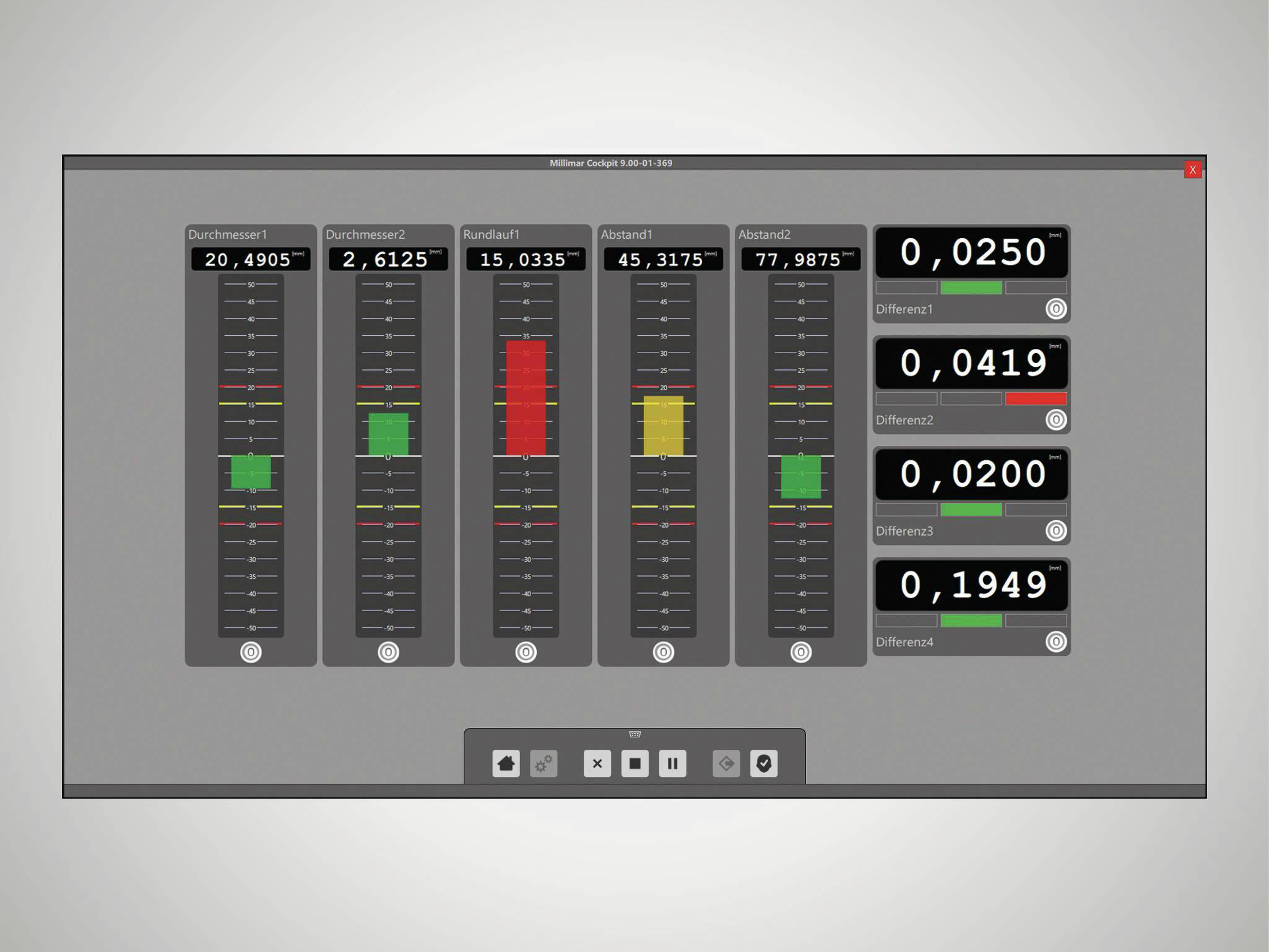
Smart and universally applicable software for complex measurement tasks in the manufacturing sector
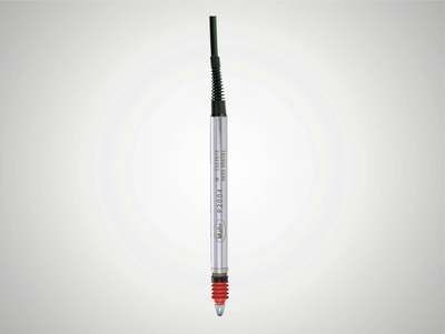
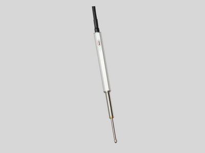
Millimar transducers are the most important components of a measuring chain. Their characteristics determine the quality of the entire measurement. Depending on the application, various technologies are available for this purpose. For example, Millimar inductive measuring probes: These products are rugged, versatile and attractively priced.
No matter whether thickness measurement, radial runout or concentricity: With the inductive probes you can record measured values and deviations independent of shape, support or radial runout deviations. Their great advantage is the large linearity range and the relative insensitivity to interference. The probes are mainly used for comparative measurements in production, but the specific tasks of the sensor can vary.
Pneumatic length measuring instruments are characterized by their high accuracy and long-term stability. Non-contact measurement with measuring nozzles does not damage the workpieces. Even workpieces that are uncleaned, oiled, lubricated or coated in lapp
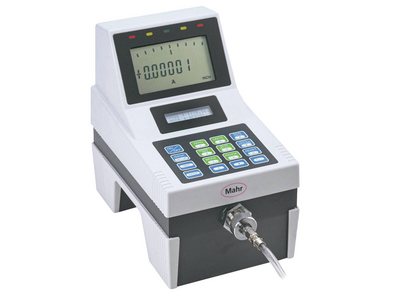
Millimar length measuring instruments are compact, robust, and easy to use. They are versatile display and evaluation devices for measuring tasks of manageable complexity in the production area.
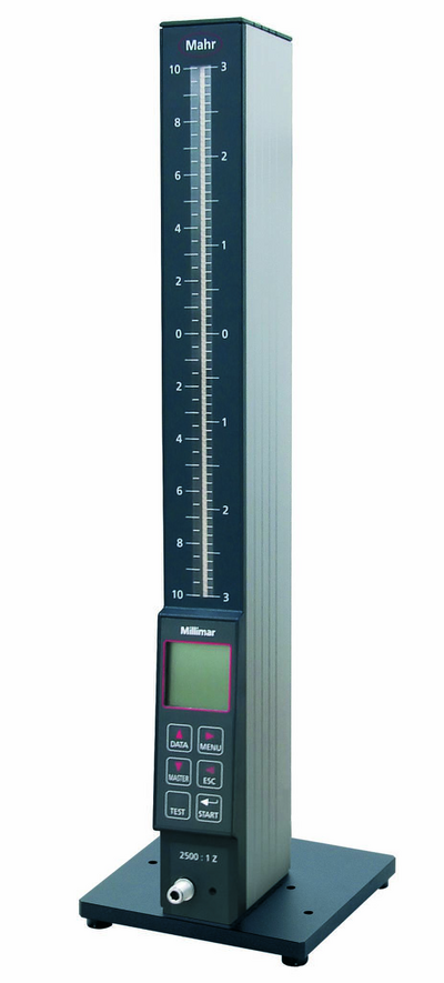
Measurement results are displayed on 101 three-color LEDs and can easily be read from a distance. If the programmable warning and tolerance limits are exceeded, the segments change colors from green to yellow or red.
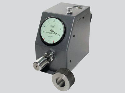
The Millimar pneumatic measuring devices quickly and accurately record dimensional deviations. It has proven itself for many years in the industrial production and measuring room.
For measurement and evaluation on the go.
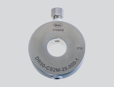
Non-contact measuring, using pneumatic measuring rings, no damage to the workpieces.
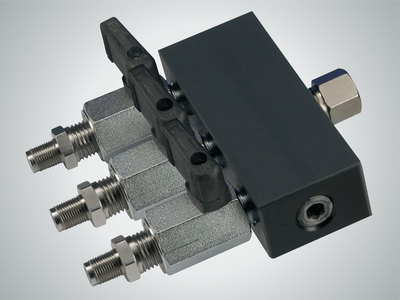
Adapt the measuring station to your measuring task with the accessories for air measuring technology.
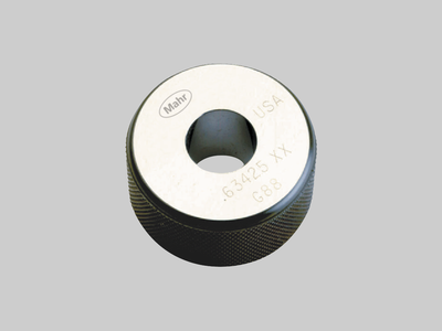
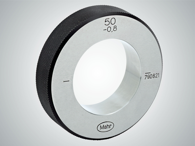
Trust in Mahr’s setting standards - because they are the basis for precise measuring results
Setting of pneumatic measuring instruments (nozzle ring gages) Meticulously hardened, aged, ground and lapped.
Setting of pneumatic measuring instruments (nozzle plug gages) Meticulously hardened, aged, ground and lapped.
Want to aim high with your measurements? Digimar is the one for you!
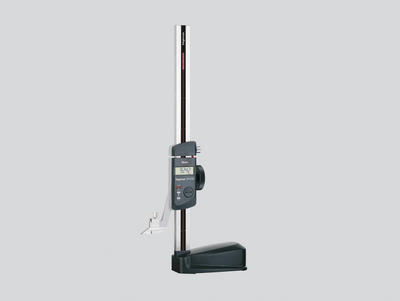
For scribing and marking workpieces in the workshop. Easy measurement of heights and distances.
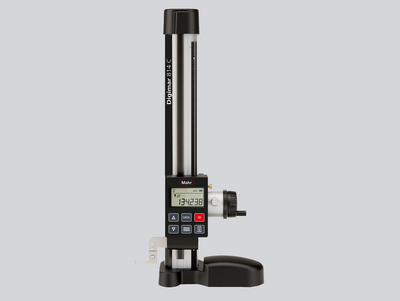
Practical measurement modes and options: The Digimar 814 C makes typical measurement tasks easy
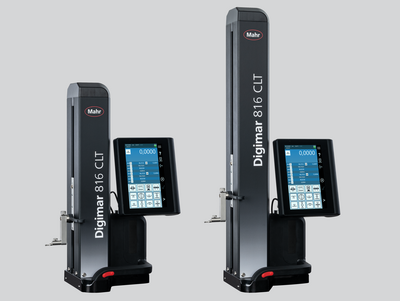
Touch operation, ergonomic handling and a wide range of evaluation options: This is what the Digimar 816 CLT height measuring device stands for.
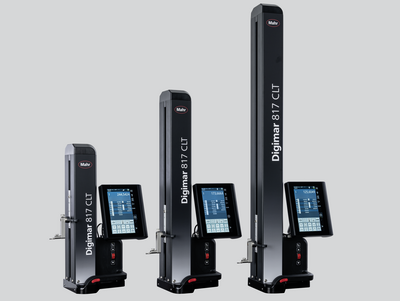
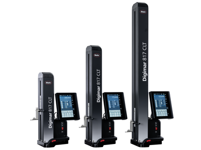
Touch operation, ergonomic handling and a wide range of evaluation options: This is what the Digimar 817 CLT height measuring device stands for.
Touch operation, ergonomic handling and a wide range of evaluation options: This is what the Digimar 817 CLT height measuring device stands for.
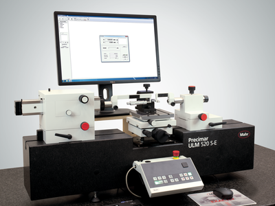
Precision length metrology stands for high-precision dimensional metrology – for both absolute and relative measurements.
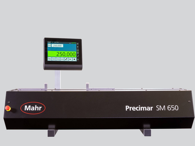
Universal, easy-to-use length measuring and setting devices for the shop floor
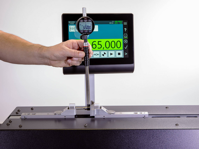
Universal, easy-to-use length measuring and setting devices for the shop floor
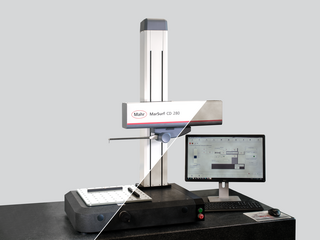
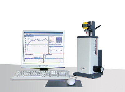
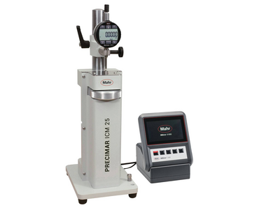
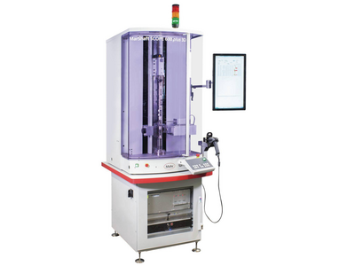
Due to the wide product range from the simple gage block test stand, fully automatic dial gage test stand, and the ULM devices to the ultra-precise and partially automated CiM universal measuring machine, Mahr always offers a practical solution for production, measuring rooms and calibration laboratories. In other words: Maximum precision combined with extremely efficient measuring processes.
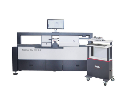
Whether classic ULM or motorized PLM and CiM instruments. Mahr universal length measuring machines enable user-friendly, fast and reliable measurement with minimal uncertainty.
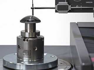
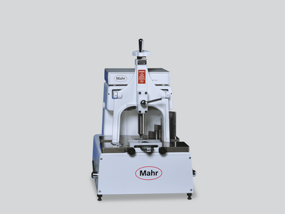
Semi-automatic and fully automatic testing of dial indicators, dial test indicator measuring devices, dial comparators and probes - efficient and precise.
Semi-automatic and fully automatic testing of dial indicators, dial test indicator measuring devices, dial comparators and probes - efficient and precise.
Manual testing of dial gages, dial test indicators and comparators - easy and precise
Trust in Mahr gage block comparators - because they are the basis for the precise testing of your standards
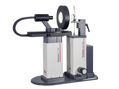
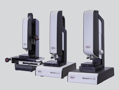
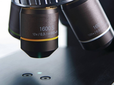
Microscopes are used in almost all industries for the quick inspection of distances, radii, and angles. In the laboratory or close to production.
For the quick evaluation of geometric elements
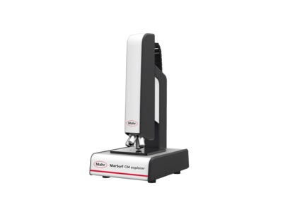
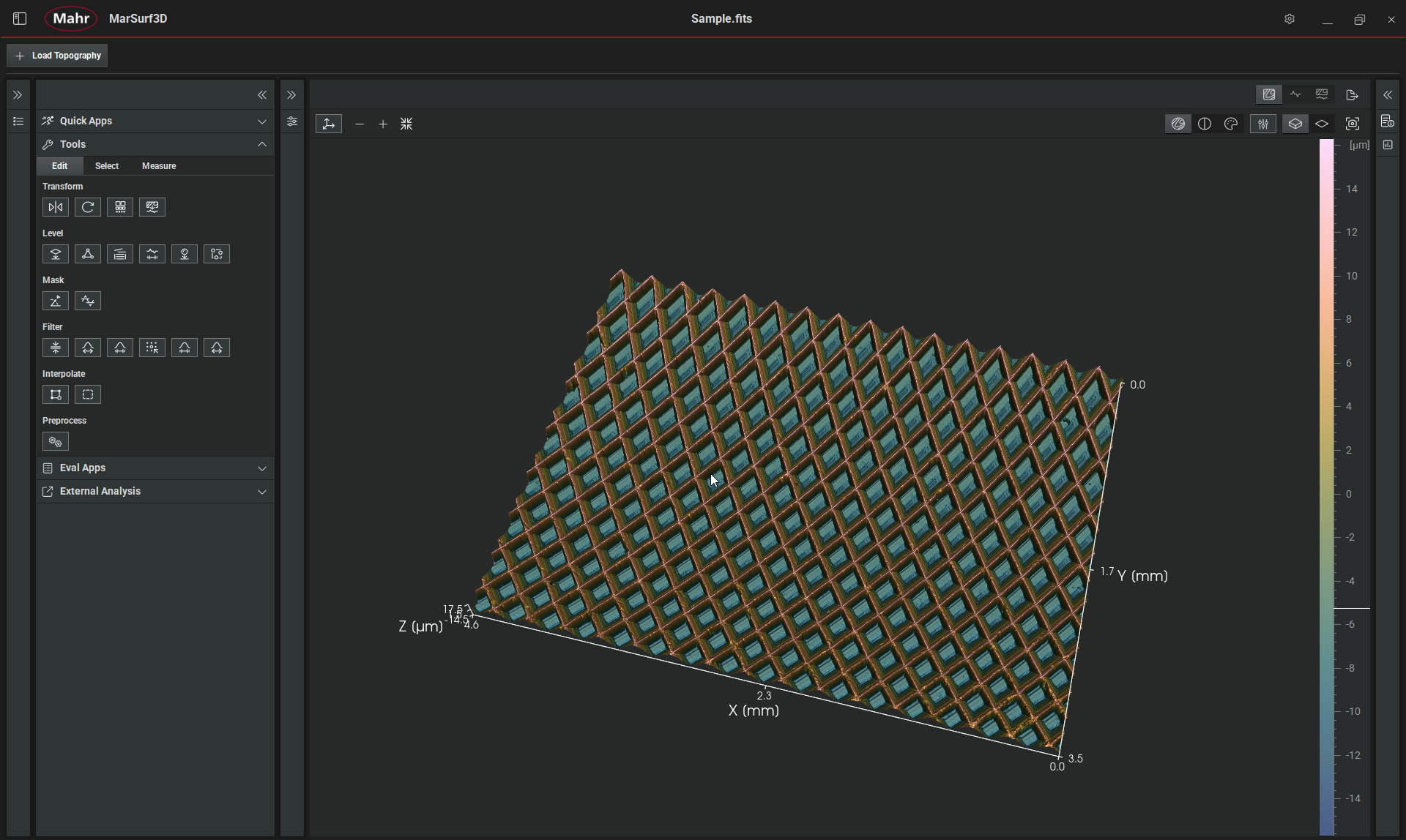
Surface metrology for industry and research
Surface metrology for industry and research
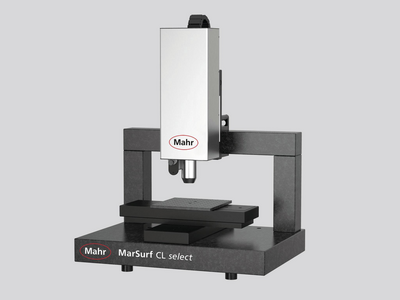
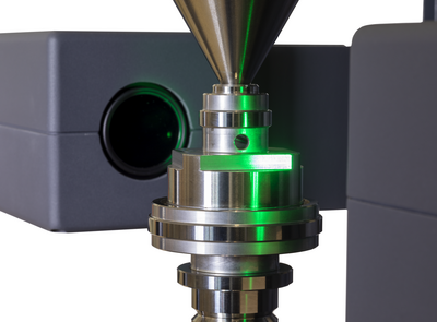
Structured functional surfaces with strict tolerances require high-precision measuring systems that record the topography of a workpiece or object over a short area in a minimum of time.
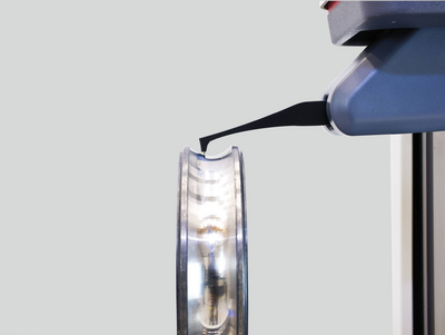
Contour measurement technology is used to determine rough shape deviations.
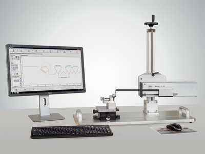
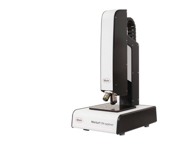
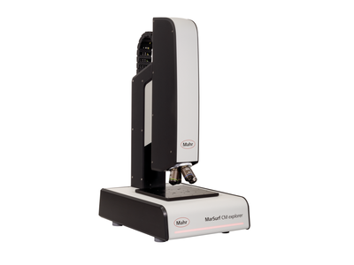
Precisely measure contours with optical measuring instruments
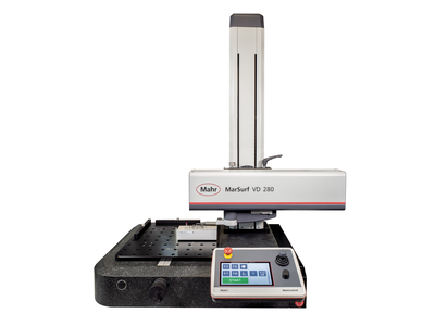
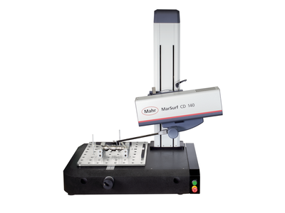
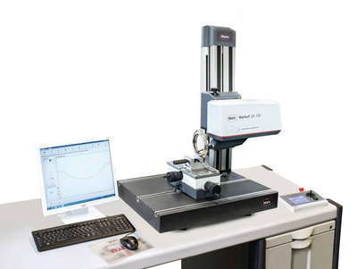
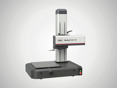
Contour and roughness measurement combined: The professional allrounder
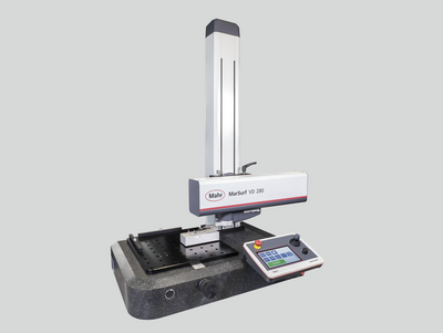
Contour and roughness measurement combined: The professional allrounder
2D/3D Contour measurement as well as roughness measurement acc. to ISO 25178 / ISO 4287
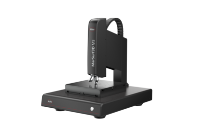
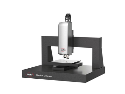
3D surface metrology for industry and research
Measure everywhere with mobile measuring devices!
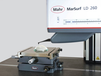
Measuring stations for the measurement of high-precision lenses
When standard solutions are no longer enough: Individual customized solutions
Structured functional surfaces with strict tolerances require high-precision measuring systems that record the topography of a workpiece or object over a short area in a minimum of time.
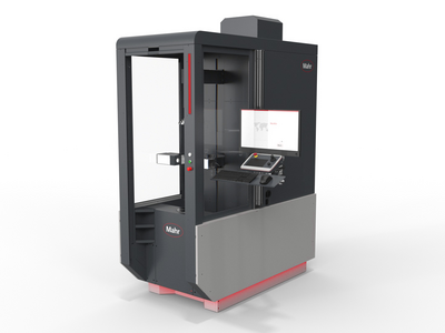
Versatile and powerful in measuring rooms and laboratories
Contour and roughness measurement combined: The professional allrounder
Tactile measuring stations for contour & roughness measurements
2D/3D contour and roughness measurement acc. to ISO 25178 / ISO 4287
3D surface metrology for industry and research
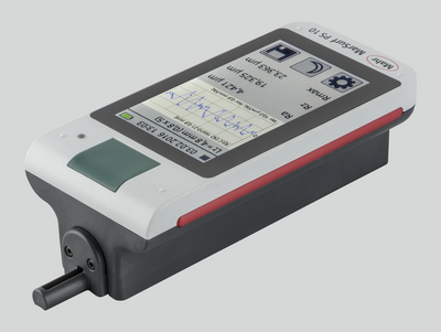
Measure everywhere with mobile measuring devices!
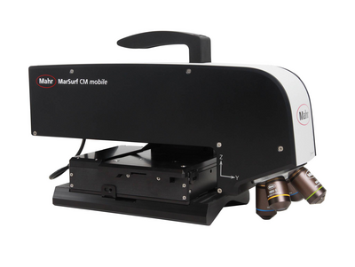
Mobile 3D surface metrology for
use on-site

Mobile measuring instruments let you measure exactly where you need the results.
Measuring stations for the measurement of ultra-high sensitivity lenses
When standard solutions are no longer enough: Individual customized solutions
Metrology
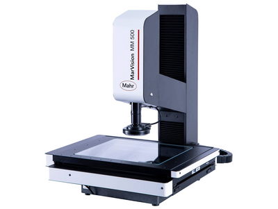
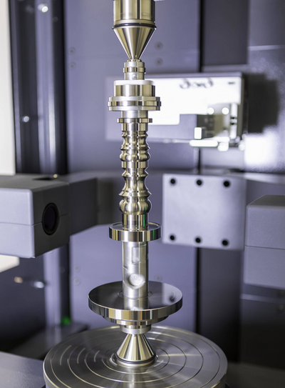
Experience outstanding features combined with extreme flexibility in workpiece size and increase your productivity in the production environment.
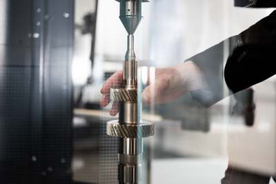
Flexible measurement of workpieces that can be clamped between centers
High resolution and very fast matrix camera for measuring a large number of features on rotationally symmetrical workpieces.
Fast optical matrix camera in combination with high-precision touch probes for measuring a large number of features on rotationally symmetrical workpieces.
Flexible clamping options and high-precision alignment using a fully automatic centering and tilting table
High resolution and very fast optical matrix camera for measuring a wide range of rotationally symmetrical workpieces. Addition of a fully automatic centering and tilting table for extremely fast, mechanical alignment and flexible clamping options.
Fast optical matrix camera in combination with high-precision touch probes for measuring a large number of features on rotationally symmetrical workpieces. Addition of a fully automatic centering and tilting table for extremely fast, mechanical alignment, flexible clamping options and, for example, internal measurements.
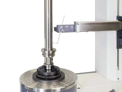
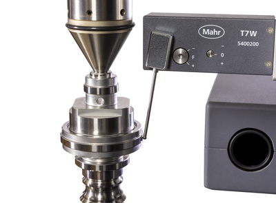
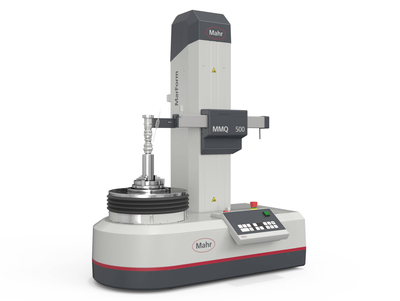
Systems for measuring form and position tolerances, such as roundness, flatness, straightness and coaxiality. From manual to fully automated.
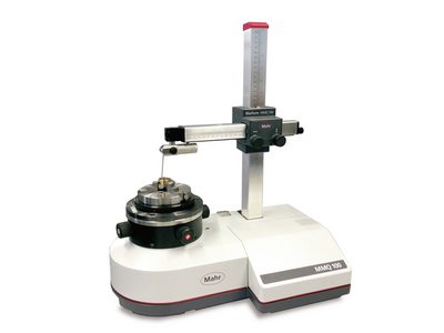
The device measure features such as roundness, straightness and concentricity simply, cost-effectively, and yet with high precision. Our manual form measuring instruments are suitable for both the measuring room and for measurements close to production.
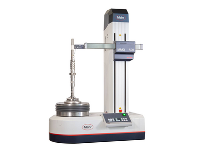
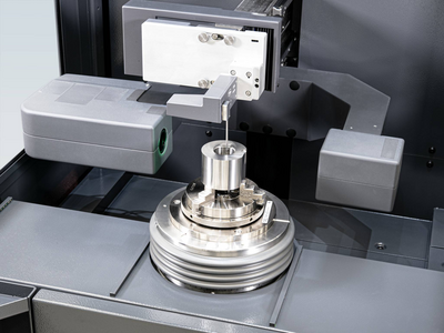
With our automatic form measuring systems, you reduce your process costs, but without driving up inspection costs – thanks to stable, innovative devices with the highest level of automation, flexibility and accuracy.
metrology
Experience outstanding features combined with extreme flexibility in workpiece size and increase your productivity in the production environment.
Flexible measurement of workpieces that can be clamped between centers
Flexible clamping options and high-precision alignment using a fully automatic centering and tilting table
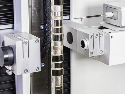
Optical and tactile shaft measurement systems for use in harsh manufacturing environments. Complete measurement of all common rotationally symmetrical workpieces.
.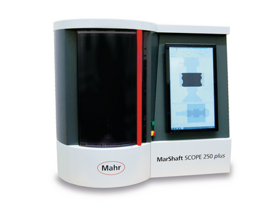
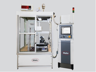
Universal, fully automatic and robust optical shaft measuring devices for use in harsh production environments.
Optical-tactile shaft measurement devices for use in harsh manufacturing environments. Complete measurements of all common rotationally symmetrical workpieces.
Metrology
Experience outstanding features combined with extreme flexibility in workpiece size and increase your productivity in the production environment.
Flexible measurement of workpieces that can be clamped between centers
Flexible clamping options and high-precision alignment using a fully automatic centering and tilting table
Wide range of technologies and products for fast and non-contact recording of surfaces and geometries.
For the quick evaluation of geometric elements
Determination of roughness, contour and many other surface parameters.
Surface metrology for industry and research
Minimal roughness accurate to the nanometer
Optical analysis of surface topographies and geometries
Surface metrology for industry and research
Surface metrology for industry and research
Refurbished systems in proven Mahr quality

MarTool calipers are characterized by essential technology and easy operation.
All this in good professional quality, at the best price!

16 E -- Simple with essential features

16 ES -- High quality with essential features
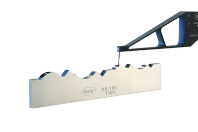
Improved standards for surface texture

When you put a sheet of paper in the printer, you don't think twice about it: The paper size fits the printer, the printer fits the paper. This is no coincidence, but the result of a standard. According to the German Institute for Standardization e. V. (DIN), around 34,000 standards currently make up the German body of standards. They provide manufacturers and consumers with important rules, set standards for products and processes, and create clear criteria – often even worldwide.
The three parts of the new body of standards DIN EN ISO 21920 are an important building block in the international standards concept of Geometric Product Specification (GPS system), which has been developed for almost 25 years. Following on from the already published standards for surface finish specification, the DIN EN ISO 25178 series of standards, DIN EN ISO 21920 also provides an updated version of the relevant profile standards. The previous profile standards
- ISO 4287:1997-04 "Parameters"
- ISO 4288:1996-08 "Measurement conditions"
- ISO 13565-1 to 3 "Load-bearing component"
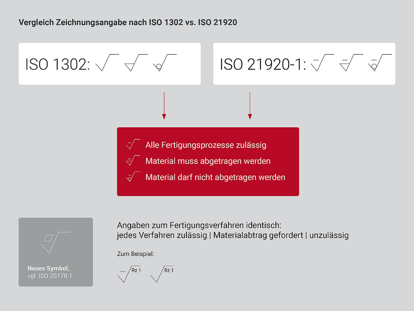
- ISO 1302:2002-02 "Drawing entries"
are being withdrawn. "They no longer cover all the possibilities of modern measuring instruments – for example, because they did not offer standardized procedures for optical measuring instruments to date. In addition, they did not always correspond to current industrial practice and in some cases had fuzziness in the definition of some parameter algorithms," explains Heinz-Joachim Kedziora, Head of Surface Metrology Development at Mahr. He is also the project manager responsible for the third part of the new standard internationally and has also taken on this task for the first part of the standard in the summer of 2021. "DIN EN ISO 12085 ("Motif") will remain; the revision of DIN EN ISO 3274 ("Stylus") has been started in the meantime."
Update and optimization
For historical reasons, some of the previous standards had quite different numbers. They ranged from "ISO 3274:1996-12 Measuring instruments" to "ISO 4287:1997-04 Parameters" and "ISO 4288:1996-08 Measurement conditions" – just to name a few. From now on, they will be summarized in the new DIN ISO 21920. It thus maps the entire process – from design to production to quality control 0 in three parts. Thus, the first part (ISO 21920-1) deals with manufacturing and specification, i.e. "drawing entries". Part 2 (ISO 21920-2) defines the parameters, and Part 3 (ISO 21920-3) formulates the conditions for checking these parameters at the end.
Part 1: Drawing ensures functions of the component
Part 1 replaces the previous ISO 1302 and covers the processes surrounding the drawing entries that a designer specifies for the manufacture of a component. The most important change: from now on, only the drawing is the basis for the conditions used to check a manufactured component. "Even if a designer develops something particularly complicated, Part 1 defines how he must specify the part without adding free text. In this way, it is possible that the specification alone ensures the function of the component," explains Heinz-Joachim Kedziora. Example: So if you only specify the parameter "Ra" and a value, then in many cases it is not ensured that this specification correlates with the functional behavior of the part. Here, there are more complex and less complex parameters. In addition, Part 1 includes new terms for the surface parameters:
| Term | Abbreviation | Explanation |
| Evaluation length | le | "evaluation length", the part of the sensing distance that is evaluated; replaces lmor ln. |
| Nesting index | Nic, Nis | "cutoff wavelength" only useful for linear filters; replaces λc and λs. |
| Profile S filter | Profile-S filter removes short wavelength components (low pass); for roughness parameters, the Nis filter("λs filter") removes very short wavelength components that do not belong to the R profile. For ripple parameters, theNic filter("λc-filter") removes short-wave components that belong to the R-profile and not to the W-profile. | |
| Profile L filter | Profile L filter removes long-wave components (high-pass); for roughness parameters, theNic filter("λc filter") removes long-wave components that do not belong to the R profile. | |
| Section length | lsc | "section length" for the parameters calculated from profile sections, e.g. Rz, Rp, Rv; replaces the term "single measurement section". |
| Number of sections | nsc | "number of sections"; replaces the term "number of individual measured sections |
Important for all users: The new standard applies only to new drawings. Older dated drawings retain their validity under the previous standard.
Also new are some symbols introduced to establish the clear reference of a drawing according to DIN EN ISO 21920-1:
Part 2: Designers are in demand
The second part of the new ISO 21920 deals with the relationship between parameters and functions of components. It is the most comprehensive and probably most difficult part and replaces the former ISO 4287. "More than 100 parameters are described here, offering designers an enormous toolbox. In the future, they will be asked to select the right parameter from this part. Experience has shown that many users find the selection difficult, as this topic is not a training focus," says the development manager.
In the case of the parameters calculated from profile elements (= a mountain and a valley in the profile), there were previously greater measurement uncertainties because the profile elements were described but not clearly defined in detail, especially in borderline cases. This has now been significantly improved. However, metrology manufacturers are not forced to program all these parameters into a device or software, since some of them only play a role regionally.
Part 3: How to arrive at a valid result
Part 3 defines the conditions according to or under which measurements are made. It replaces the previous ISO 4288 and deals with the subject of "Specification and Verification" – i.e. requirements for measurement procedures and their correct implementation. Part 3thus defines the default case. This means that if no explicit specifications are made in the drawing, what is in the standard applies – in other words, everything that does not have to be explicitly specified.
"So this part is not only about the measurement conditions, but also about additional factors to be taken into account, how to get a valid result. Therefore, there are no prescriptions in this part on how to measure something, but only the description of a complete specification operator," Kedziora explains. The specification is theoretically ideal and unambiguous. According to ISO 8015, "The verification operator is the physical implementation of the specification operator. It can have exactly the same operations in the same order (in which case the procedural uncertainty is zero) or it can have different operations or perform the operations in a different order (in which case the procedural uncertainty is not zero)."
For verifcation, therefore, one simply specifies the uncertainty, which is not easy in practice for the most part. As an example, consider the use of the Gaussian filter: If in the standard case the specification assumes a profile point spacing of 0.5 µm, it is not forbidden to use a larger or smaller point spacing during verification; the user must then take this into account when estimating the measurement uncertainty.
Conclusion: Expanded possibilities for function descriptions
For most users, the new standard changes nothing at all. It only offers extended possibilities for functional descriptions, for example in additive manufacturing processes, where new structures or new filters are sometimes required.
Unlike in the past, it is no longer the workpiece that determines the filter setting, but the associated drawing. This increases the reliability of the decision as to whether the tested surface meets the requirements or not. There is no longer any need for the time-consuming – and in practice hardly observed –procedure according to DIN EN ISO 4288 for inspecting a workpiece surface, including the subjective assessment of whether a profile is periodic or aperiodic.
Overall, great emphasis was placed on continuity in the new standard. "The bottom line is that the weak points of the old standard – such as imprecise and non-practical definitions – have been eliminated. Where the old standard delivered reasonable results, this also applies to the new standard. Where the old standard was fuzzy, the new standard is sharper," summarizes development manager Kedziora. "Due to the continuity by which the new profile standard retains everything that has proven itself in industrial practice, users can continue to measure in accordance with the standard even with their existing measuring devices."
Currently, the German Institute for Standardization e. V. (DIN) is drafting the national standards DIN EN ISO 21920-1, -2 and -3. It is strongly recommended that the editions DIN EN ISO 21920-1, -2 and -3, which were published as early drafts as early as 2020, be withdrawn from circulation, as there were still changes in the international discussion leading up to the final version of the series of standards.

Tip:
Mahr is devoting a comprehensive webinar to the new ISO 21920 under the name "New Surface Standard". What the new standard has in store for metrologists and users is explained clearly and in detail. > View seminar
The changes at a glance:
- A few new terms
- New symbol for the specification
- The default tolerance acceptance rule is the maximum value rule ("max. rule").
- The rule values are based on the specification (drawing entry) and not on estimated values of the specified parameter. As a result, the assignment of nesting index is somewhat shifted depending on the specified Ra or Rz value.
- If nothing else is specified, verification is performed at the location of the specified geometry element where the maximum values are expected; imperfections such as scratches or pores must be included.
- No distinction between periodic and aperiodic profiles
- Parameters are (with a few exceptions) defined by the evaluation section.
- Only a few parameters, e.g. Rz, Rp, Rv are defined via profile sections (the term "sampling length" or "single measuring section" is no longer used).
- The specification of the tolerance limit follows immediately after the parameter designation.
- Simplified notation for the specification of bilateral tolerance limits
- A third tolerance acceptance rule: "Tmed": The median value of all measured values must lie within the specified tolerance limits.
- The specification of optical methods for profile acquisition is possible, e.g. EP OR(1).