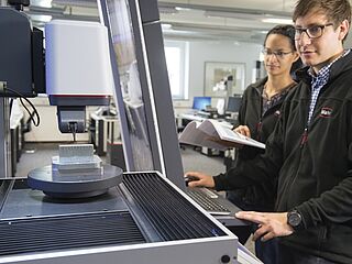
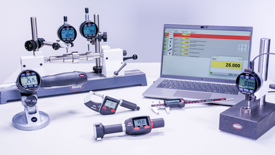
High-quality metrology for quality control in the measuring room, production, incoming goods and development.
Gear Metering Pumps & Meter Mix Dispense Machines with highest accuracy for processing liquids and pastes.
High-precision rotary stroke bearings for backlash-free linear and rotational movements for use in machine and device construction.


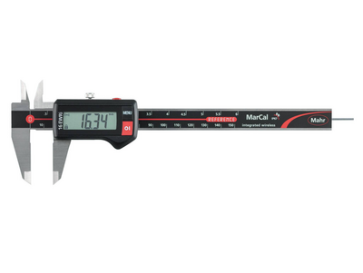
Innovative handheld measuring equipment from Mahr: Calipers, micrometers and dial indicators from analog to digital models with integrated wireless transmission. Mahr's comparative measuring instruments and reference standards are indispensable for your precise production metrology.
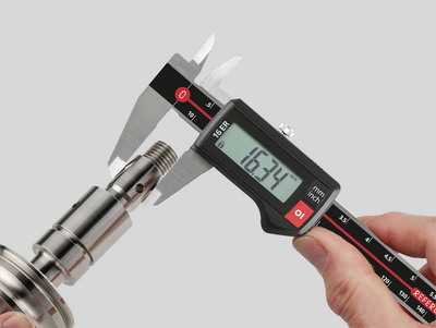
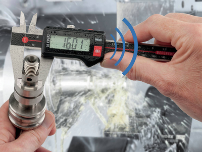
From analog to digital, the entire spectrum of calipers. Easy handling, wireless, and highly accurate. Perfect for efficient use in manufacturing.
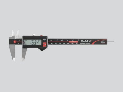
A safe, easy to read digital display, the modern design and the usual Mahr accuracy characterize our digital calipers. The range includes measuring instruments for all applications. Various interfaces for data transmission and protection rating up to IP 67 leave no demands unfulfilled.
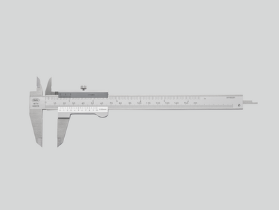
Glare-free reading, hardened steel, raised guideways to protect the scale and provide the highest accuracy. Features of a quality caliper from Mahr with the classic vernier caliper.
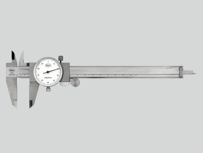
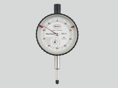
Large, high-contrast dial and shock-protected measuring tool for lasting precision. A tried and tested mechanical design for fast and safe reading.
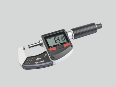
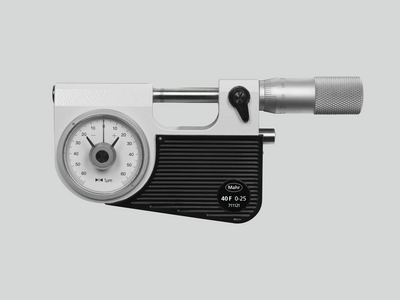
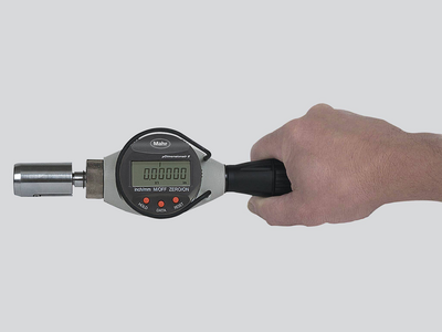
Maximum precision in a variety of designs. Micrometers from Mahr are available in conventional mechanical and digital and wireless versions.
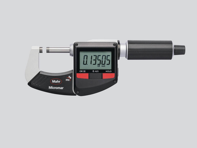
A clear digital display, modern design and the usual Mahr accuracy characterize our digital outside micrometers. The range includes measuring instruments for all applications. Various interfaces for data transmission and a high protection rating up to IP 65 leave no demands unfulfilled.
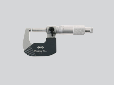
Anti-glare reading, thermal insulation plates and a precision-ground spindle for maximum accuracy. Features of a quality micrometer from Mahr.
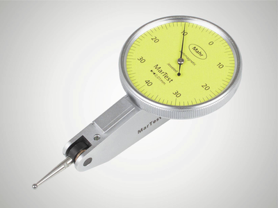
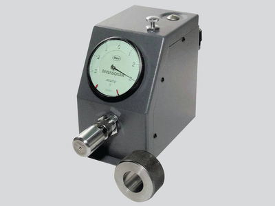
Particularly suitable for reliable and fast testing of series parts (shafts, bolts, shanks). The dimensional accuracy is recognized and read at a glance on the dial comparator.
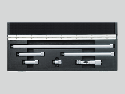
Suitable for measuring large diameters and testing distances up to 2,500 mm
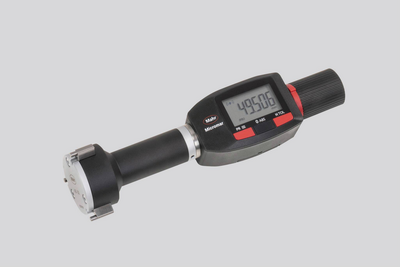
Available with scale or digital display or as a quick-measuring instrument with pistol-type grip. The Mahr 3-point inner measuring devices always provide reliable measuring results due to automatic self-centering.
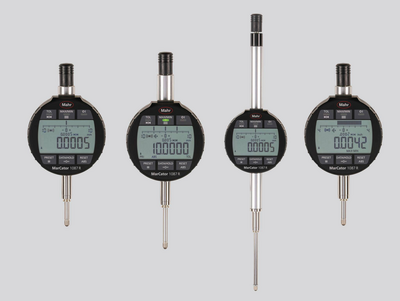
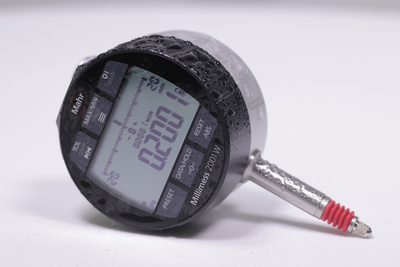
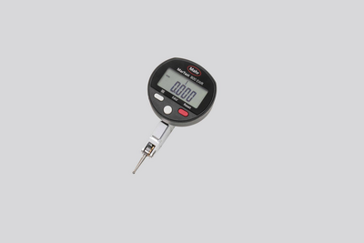
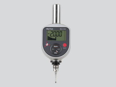
From analog to digital, the entire spectrum of dial gages, dial comparators and dial test indicators. Easy handling, wireless (optionally), and highly accurate. Perfect for efficient use in manufacturing.
A clear digital display, robust construction and high Mahr accuracy characterize our digital dial gages. The range includes measuring instruments for all applications. Various interfaces for data transfer and a high protection rating up to IP 54 leave no demands unfulfilled.
High sensitivity and accuracy due to: Solid mounting of the measuring tool axes, precision-geared wheels and pinions, high-precision mounted measuring pin.
Compared to analog dial indicators, Millimess dial comparators have even more precise components, providing better measuring accuracy and a much improved hysteresis error. These advantages are particularly evident in runout tests, straightness and flatness measurements and comparative measurements.
The high-precision inductive Millimess dial comparators are capable of digital increments of up to 0.2 μm. User-friendly operating functions such as tolerance monitoring, minimum or maximum recording for dynamic measurements, a combined numerical and scale display and simple data transfer make it an indispensable precision measuring instrument.
The sensitive computer-optimised measuring tool ensures maximum reliability and precision. For rough workshop use, the display is superbly protected against scratching or breakage by a hardened mineral glass pane, and a seal also provides reliable protection against penetrating liquids.
The sensitive computer-optimised measuring tool ensures maximum reliability and precision. For rough workshop use, the display is superbly protected. A seal also provides reliable protection against penetrating liquids.
Mahr 3D measuring probes for NC machines, machining centers and eroding machines shorten setup and downtimes. Perfect for accurately contacting reference edges on workpieces and fixtures.
Whether Integrated Wireless, external wireless modules, USB, Opto RS232, or Digimatic: Regardless of which interface standard you use, MarConnect will always provide the best connection.
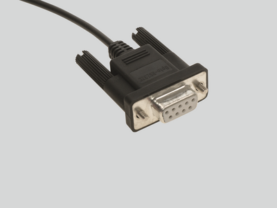
Many Mahr precision gages have a data output with MarConnect interface. Regardless of which interface standard you use, (USB, Opto RS232 or Digimatic), MarConnect will always provide the best connection.
Mahr’s Wireless range guarantees you precise measuring results with full mobility. The modern and easy way to measure – without the restrictions of wired technology.
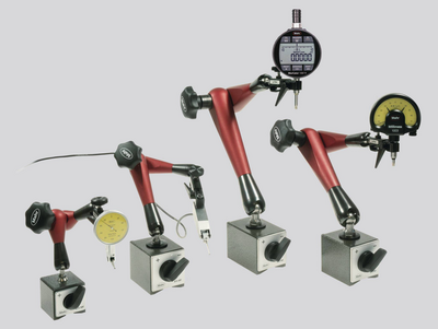
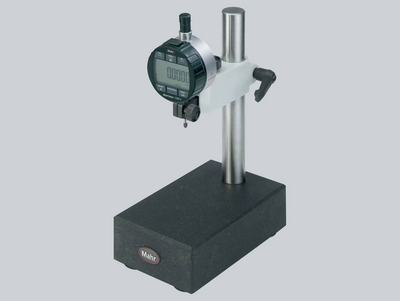
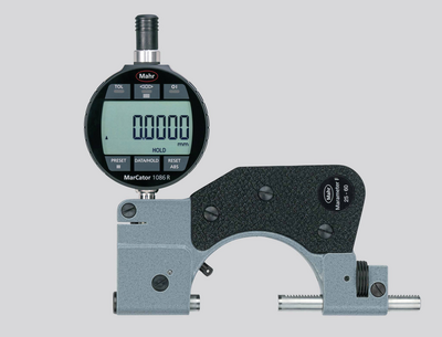
MarStand measuring tripods, measuring tables and radial run-out gages offer high stability, the basis for precise measuring results. They offer the necessary support for your dial indicators, dial comparators, dial test indicator measuring devices and measuring probes.
Measuring tripods provide the basis for precise measuring results due to their stable design. They offer the necessary support for your dial indicators, dial comparators, dial test indicator measuring devices and measuring probes.
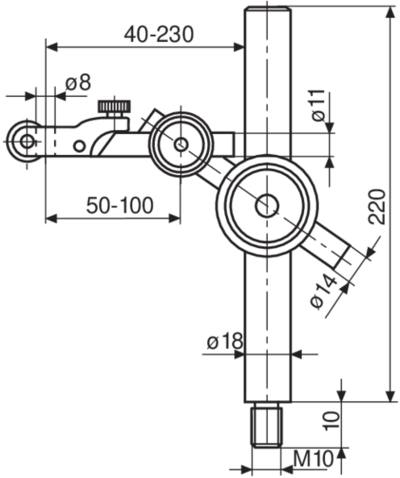
MarStand post and support assemblies are used for individual solutions and offer high stability, the basis for precise measuring results. They offer the necessary support for dial indicators, dial comparators, dial test indicator measuring devices and measuring probes.
Measuring tables combine a precise and level measuring table, a stable measuring column and strong arm parts. MarStand measuring tables provide the basis for precise measuring results due to their extra stable design.
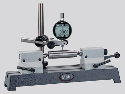
Radial run-out gages are the simplest method of detecting positional and form errors on shafts in a close-to-production environment. Due to the variety of models, the robust MarStand radial run-out gages form the basis for a wide range of workpiece requirements and precise measuring results.
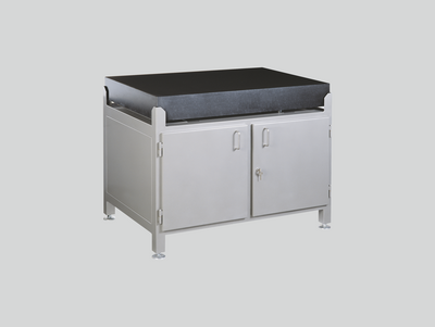
Test plates made of hard granite are the perfect surface for your height measurement instruments due to the plates’ high strength and dimensional stability.
Using indicating gages as comparative gages make the perfect tool for precision measurements in manufacturing. Setting the gage to a reference standard reduces the deviation margin and minimizes the influence of temperature fluctuations on the measurement result.
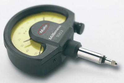
Indicating snap gages are the perfect measuring tools for precision measurements of cylindrical parts such as shafts, bolts and shanks, especially for safe and fast tests on series parts. The dimensional accuracy is identified and read at a glance on the dial comparator.
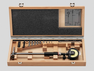
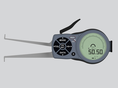
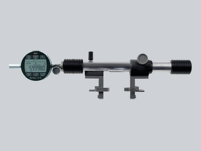
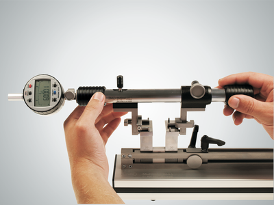
Inner measuring devices are the perfect tools for precisely measuring the diameter, roundness and conicity of holes.
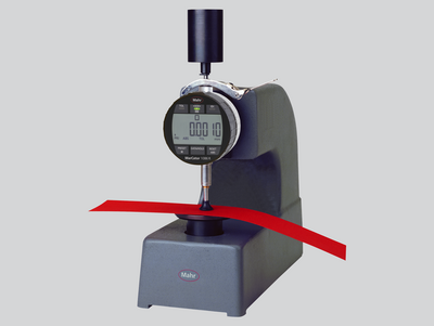
Our thickness gages offer a robust and simple range for particularly fast measurement of a variety of films, sheets, and plates.
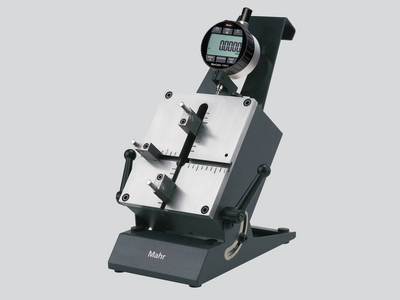
If common measuring instruments such as calipers or inner micrometer screws cannot be used due to the workpiece geometry, caliper gages are the perfect solution!
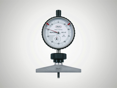
Our depth gages offer a robust and simple range for particularly fast depth measurements. The 8mm mounting shaft allows the use of dial indicators, dial comparators and probes according to the measuring task.
Universal measuring instruments are the perfect partners for precision measurements in production, because the comparison measurement to a reference standard minimizes the influence of temperature fluctuations on the measurement result.
No matter whether gear, thread, taper or recess: Multimar universal measuring instruments are an ideal solution for almost all internal and external measurements for which standard measuring instruments are not suitable. A choice of basic units and an extensive range of accessories are available.
Accurately adjust your inside and outside measuring instruments. When using the 844 S setting instruments, you are perfectly equipped for every measuring task - even for larger dimensions.
No matter whether centering shoulders, narrow collars or recesses: The Multimar 36B universal measuring instruments are an ideal solution for almost all inner and outer measurements. A choice of basic units and an extensive range of accessories are available.
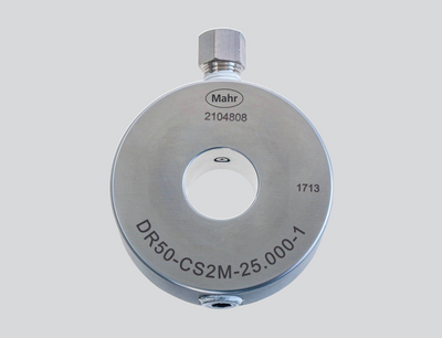
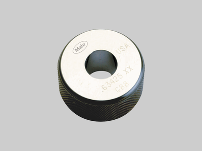
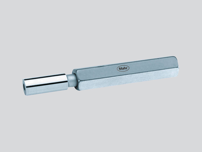
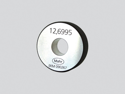
Trust in Mahr setting standards and gages – because they are the basis for precise measuring results.
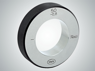
Trust in Mahr’s setting standards - because they are the basis for precise measuring results.
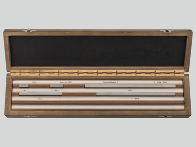
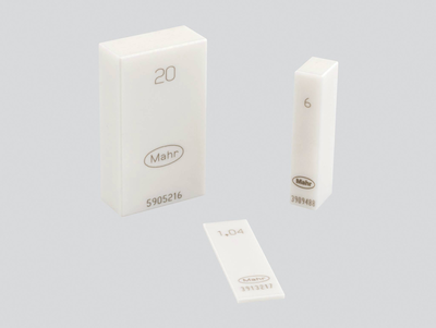
Mahr gage blocks ensure that you have high-quality reference and working standards at your disposal. Choose from four tolerance classes and two materials to suit the requirements of your workshop, production or quality assurance.
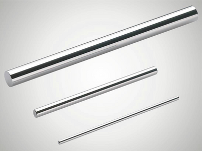
Mahr pin gages are available in three tolerance classes and various designs. Choose the device to suit the requirements of your workshop, production or quality assurance.
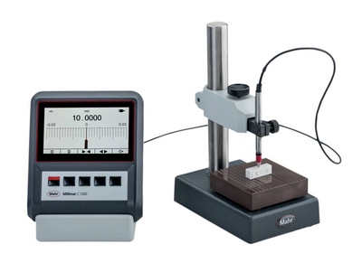
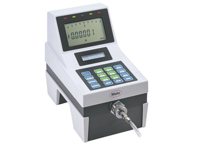
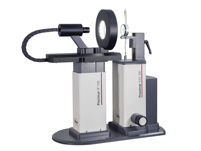
The requirements for electrical length measuring instruments are just as varied as their applications. Excellent reliability, precision and simple operation are called for.
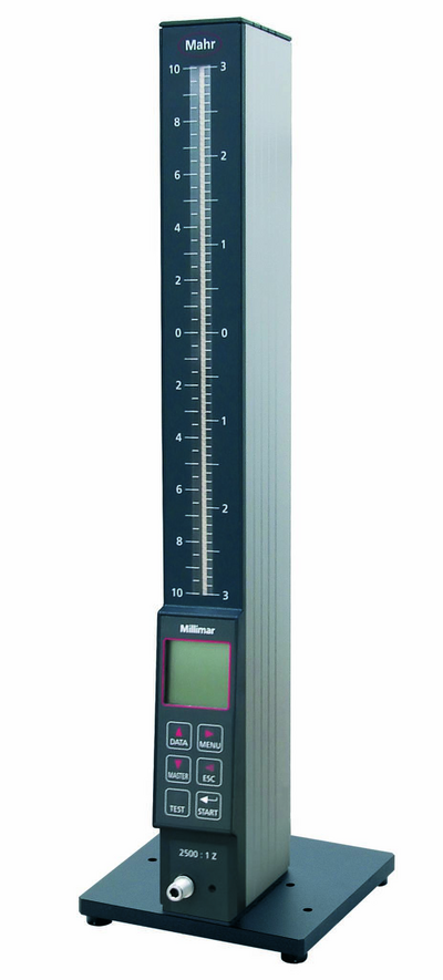
The requirements for electrical length measuring instruments are just as varied as their applications. Excellent reliability, precision and simple operation are called for. Millimar compact and column measuring instruments meet these requirements.
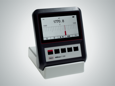
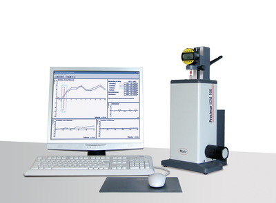
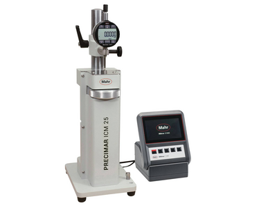
Millimar length measuring instruments are compact, robust, and easy to use. They are versatile evaluation and indicating instruments for measuring tasks of manageable complexity in the production area and in the measuring room.
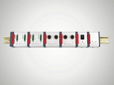
The diverse combination options of modules and software provide the opportunity to design a working environment and tools more individually than ever before.
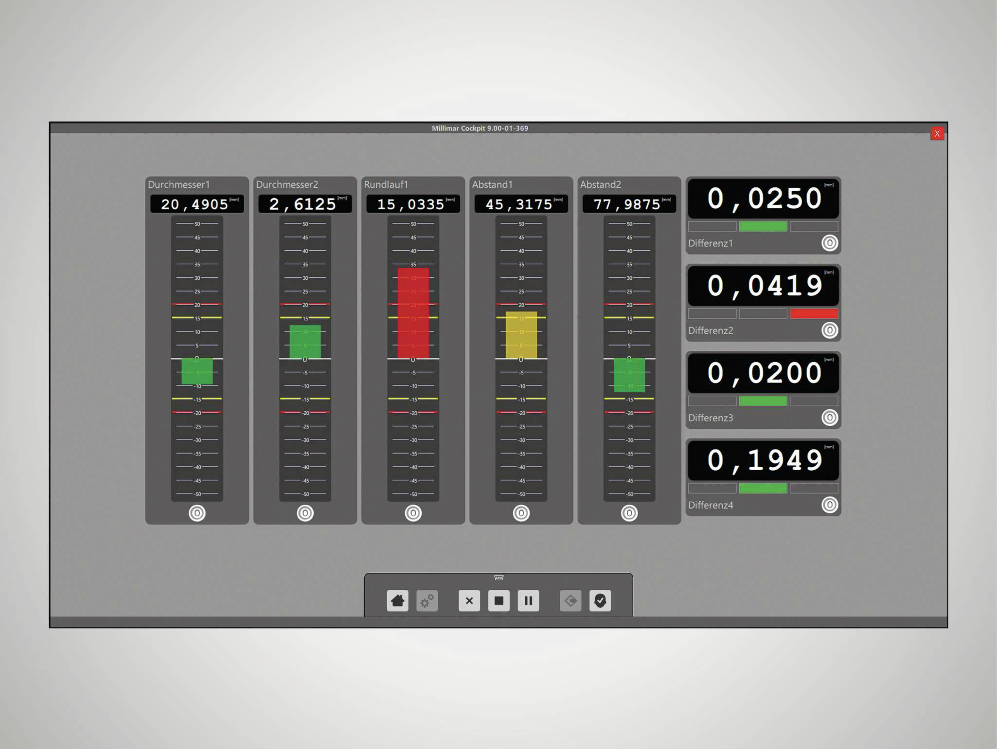
Smart and universally applicable software for complex measurement tasks in the manufacturing sector
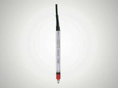
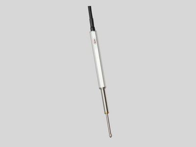
Millimar transducers are the most important components of a measuring chain. Their characteristics determine the quality of the entire measurement. Depending on the application, various technologies are available for this purpose. For example, Millimar inductive measuring probes: These products are rugged, versatile and attractively priced.
No matter whether thickness measurement, radial runout or concentricity: With the inductive probes you can record measured values and deviations independent of shape, support or radial runout deviations. Their great advantage is the large linearity range and the relative insensitivity to interference. The probes are mainly used for comparative measurements in production, but the specific tasks of the sensor can vary.
Pneumatic length measuring instruments are characterized by their high accuracy and long-term stability. Non-contact measurement with measuring nozzles does not damage the workpieces. Even workpieces that are uncleaned, oiled, lubricated or coated in lapp
Millimar length measuring instruments are compact, robust, and easy to use. They are versatile display and evaluation devices for measuring tasks of manageable complexity in the production area.
Measurement results are displayed on 101 three-color LEDs and can easily be read from a distance. If the programmable warning and tolerance limits are exceeded, the segments change colors from green to yellow or red.
The Millimar pneumatic measuring devices quickly and accurately record dimensional deviations. It has proven itself for many years in the industrial production and measuring room.
For measurement and evaluation on the go.
Non-contact measuring, using pneumatic measuring rings, no damage to the workpieces.
Adapt the measuring station to your measuring task with the accessories for air measuring technology.
Trust in Mahr’s setting standards - because they are the basis for precise measuring results
Setting of pneumatic measuring instruments (nozzle ring gages) Meticulously hardened, aged, ground and lapped.
Setting of pneumatic measuring instruments (nozzle plug gages) Meticulously hardened, aged, ground and lapped.
Want to aim high with your measurements? Digimar is the one for you!
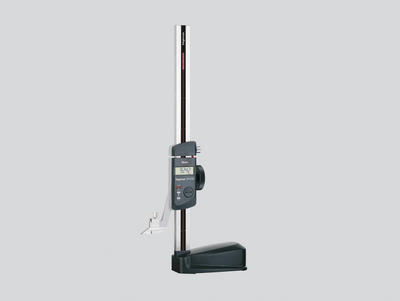
For scribing and marking workpieces in the workshop. Easy measurement of heights and distances.
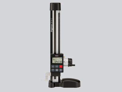
Practical measurement modes and options: The Digimar 814 C makes typical measurement tasks easy
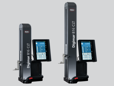
Touch operation, ergonomic handling and a wide range of evaluation options: This is what the Digimar 816 CLT height measuring device stands for.
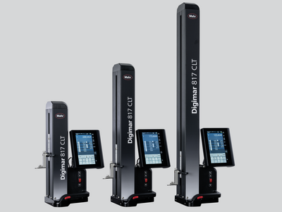
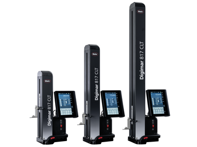
Touch operation, ergonomic handling and a wide range of evaluation options: This is what the Digimar 817 CLT height measuring device stands for.
Precision length metrology stands for high-precision dimensional metrology – for both absolute and relative measurements.
Universal, easy-to-use length measuring and setting devices for the shop floor
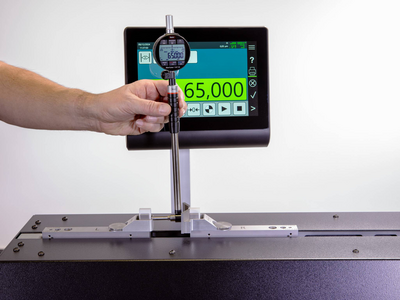
Universal, easy-to-use length measuring and setting devices for the shop floor
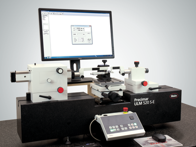
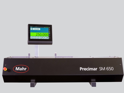
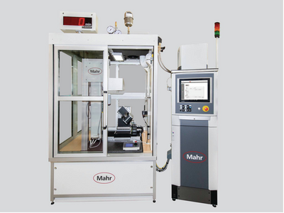
Due to the wide product range from the simple gage block test stand, fully automatic dial gage test stand, and the ULM devices to the ultra-precise and partially automated CiM universal measuring machine, Mahr always offers a practical solution for production, measuring rooms and calibration laboratories. In other words: Maximum precision combined with extremely efficient measuring processes.
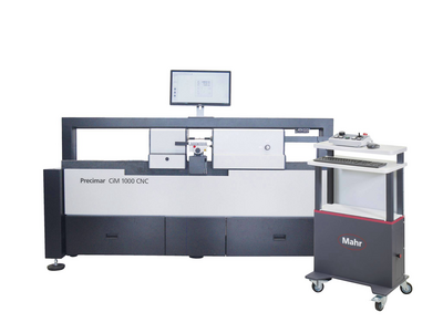
Whether classic ULM or motorized PLM and CiM instruments. Mahr universal length measuring machines enable user-friendly, fast and reliable measurement with minimal uncertainty.
Semi-automatic and fully automatic testing of dial indicators, dial test indicator measuring devices, dial comparators and probes - efficient and precise.
Semi-automatic and fully automatic testing of dial indicators, dial test indicator measuring devices, dial comparators and probes - efficient and precise.
Manual testing of dial gages, dial test indicators and comparators - easy and precise
Trust in Mahr gage block comparators - because they are the basis for the precise testing of your standards
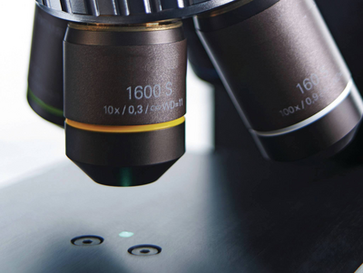
Microscopes are used in almost all industries for the quick inspection of distances, radii, and angles. In the laboratory or close to production.
For the quick evaluation of geometric elements
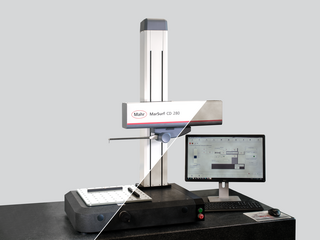
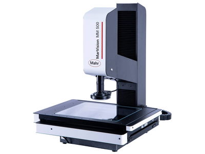
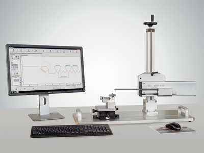
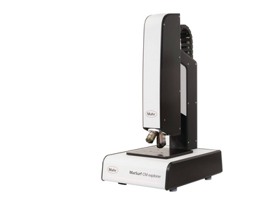
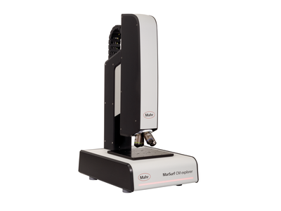
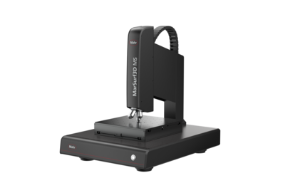
Surface metrology for industry and research
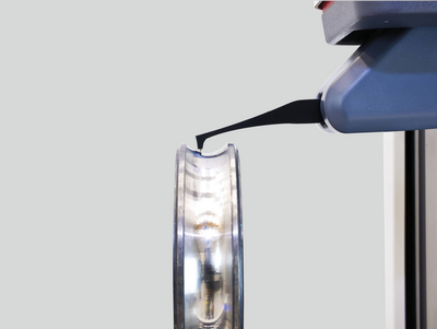
Structured functional surfaces with strict tolerances require high-precision measuring systems that record the topography of a workpiece or object over a short area in a minimum of time.
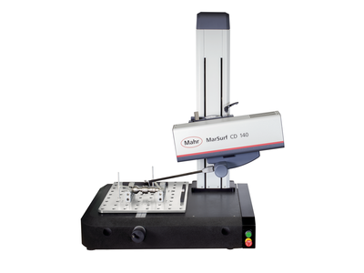
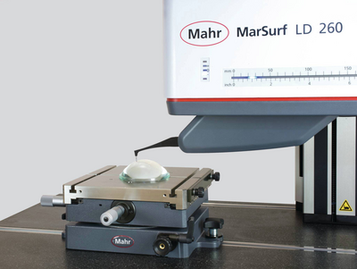
Contour measurement technology is used to determine rough shape deviations.
Precisely measure contours with optical measuring instruments
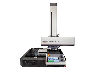
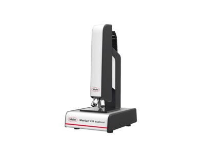
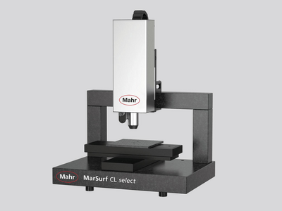
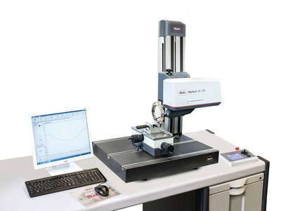
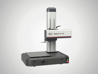
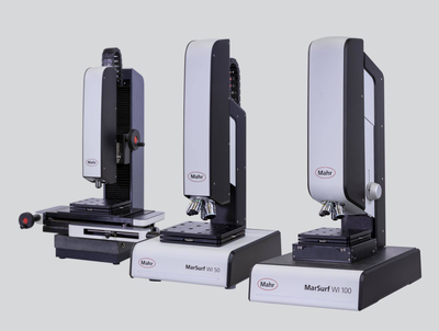
Contour and roughness measurement combined: The professional allrounder
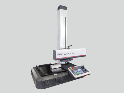
Contour and roughness measurement combined: The professional allrounder
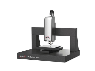
2D/3D Contour measurement as well as roughness measurement acc. to ISO 25178 / ISO 4287
3D surface metrology for industry and research
Measure everywhere with mobile measuring devices!
Measuring stations for the measurement of high-precision lenses
When standard solutions are no longer enough: Individual customized solutions
Structured functional surfaces with strict tolerances require high-precision measuring systems that record the topography of a workpiece or object over a short area in a minimum of time.
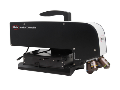
Versatile and powerful in measuring rooms and laboratories
Contour and roughness measurement combined: The professional allrounder
Tactile measuring stations for contour & roughness measurements
2D/3D contour and roughness measurement acc. to ISO 25178 / ISO 4287
3D surface metrology for industry and research
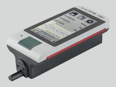
Measure everywhere with mobile measuring devices!
Mobile 3D surface metrology for
use on-site

Mobile measuring instruments let you measure exactly where you need the results.
Measuring stations for the measurement of ultra-high sensitivity lenses
When standard solutions are no longer enough: Individual customized solutions
Metrology
Experience outstanding features combined with extreme flexibility in workpiece size and increase your productivity in the production environment.
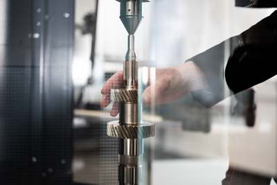
Flexible measurement of workpieces that can be clamped between centers
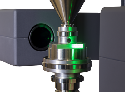
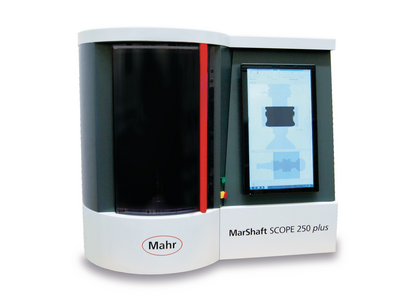
High resolution and very fast matrix camera for measuring a large number of features on rotationally symmetrical workpieces.
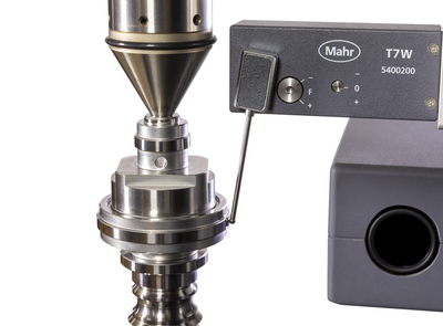
Fast optical matrix camera in combination with high-precision touch probes for measuring a large number of features on rotationally symmetrical workpieces.
Flexible clamping options and high-precision alignment using a fully automatic centering and tilting table
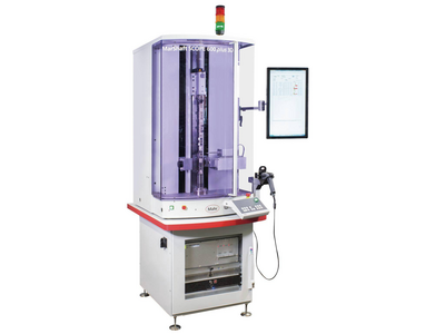
High resolution and very fast optical matrix camera for measuring a wide range of rotationally symmetrical workpieces. Addition of a fully automatic centering and tilting table for extremely fast, mechanical alignment and flexible clamping options.
Fast optical matrix camera in combination with high-precision touch probes for measuring a large number of features on rotationally symmetrical workpieces. Addition of a fully automatic centering and tilting table for extremely fast, mechanical alignment, flexible clamping options and, for example, internal measurements.
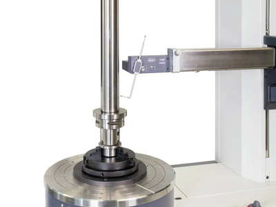
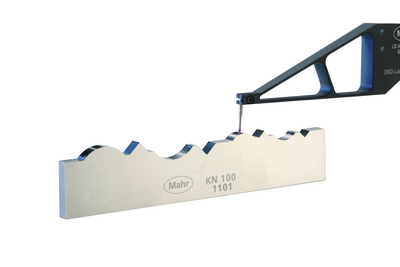
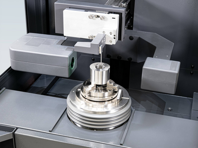
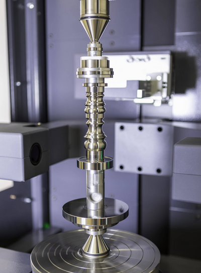
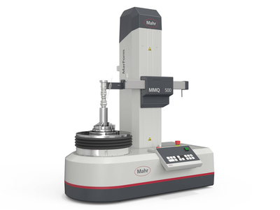
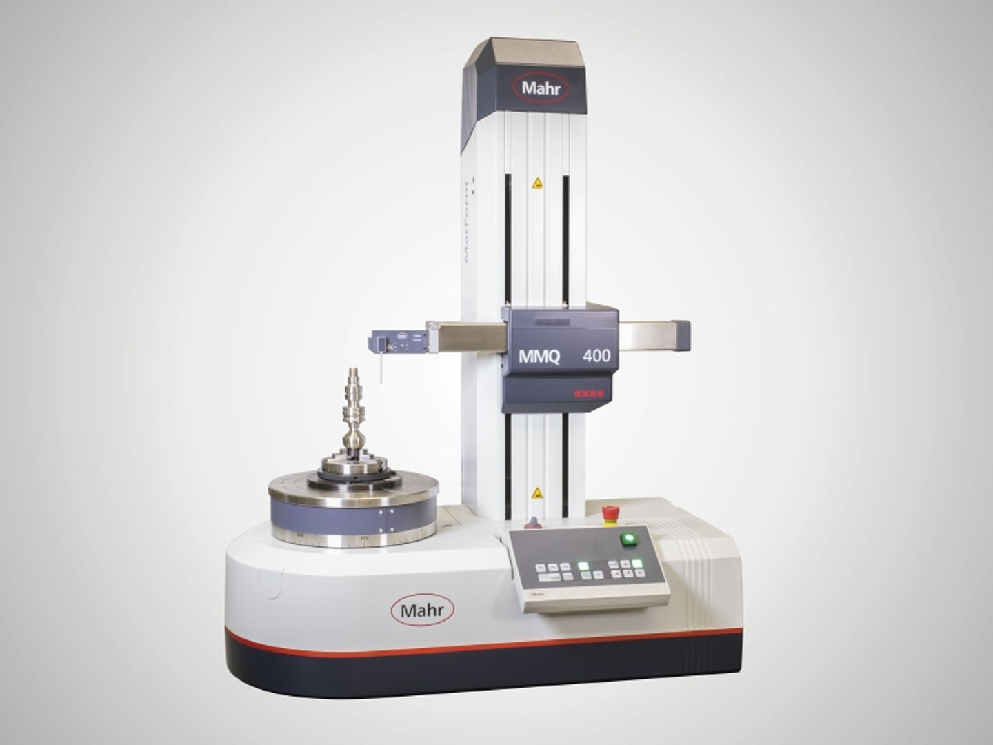
Systems for measuring form and position tolerances, such as roundness, flatness, straightness and coaxiality. From manual to fully automated.
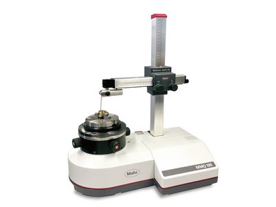
The device measure features such as roundness, straightness and concentricity simply, cost-effectively, and yet with high precision. Our manual form measuring instruments are suitable for both the measuring room and for measurements close to production.
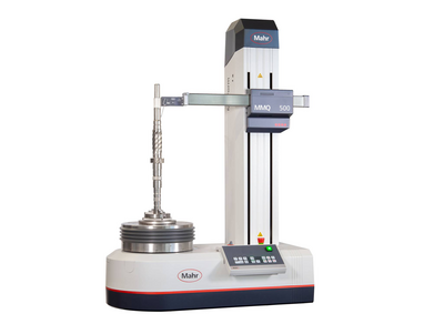
With our automatic form measuring systems, you reduce your process costs, but without driving up inspection costs – thanks to stable, innovative devices with the highest level of automation, flexibility and accuracy.
metrology
Experience outstanding features combined with extreme flexibility in workpiece size and increase your productivity in the production environment.
Flexible measurement of workpieces that can be clamped between centers
Flexible clamping options and high-precision alignment using a fully automatic centering and tilting table
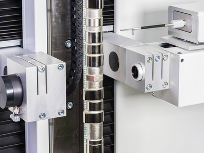
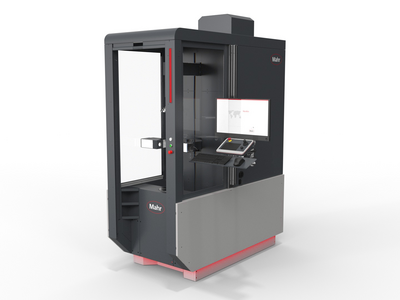
Optical and tactile shaft measurement systems for use in harsh manufacturing environments. Complete measurement of all common rotationally symmetrical workpieces.
.
Universal, fully automatic and robust optical shaft measuring devices for use in harsh production environments.
Optical-tactile shaft measurement devices for use in harsh manufacturing environments. Complete measurements of all common rotationally symmetrical workpieces.
Metrology
Experience outstanding features combined with extreme flexibility in workpiece size and increase your productivity in the production environment.
Flexible measurement of workpieces that can be clamped between centers
Flexible clamping options and high-precision alignment using a fully automatic centering and tilting table
Wide range of technologies and products for fast and non-contact recording of surfaces and geometries.
For the quick evaluation of geometric elements
Determination of roughness, contour and many other surface parameters.
Surface metrology for industry and research
Minimal roughness accurate to the nanometer
Optical analysis of surface topographies and geometries
Surface metrology for industry and research
Refurbished systems in proven Mahr quality
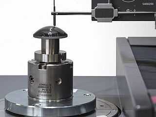
Form measurement: Understanding common problems

In the simplest case, the form measurement includes a probe and probe arm with probe element. This is moved along an ideal circular or linear path to capture the data from the stylus movements relative to this ideal geometry. The analysis is usually quite manageable: the measured data points are filtered and mathematical operations performed on them to determine the results. Although it is one of the most basic measurements to support many manufacturing processes, some steps are often performed incorrectly. Particularly common errors occur when choosing the filter and the probe element.
Using the wrong filters
Historically, 50 upr was used as the default value for roundness measurements. Although this filter may be suitable for many applications, it is not suitable for all of them. The new DIN EN ISO 1101: 2017-09 makes it possible to specify a suitable filter setting directly with each form tolerance in the drawing. Nevertheless, the filter must still be chosen based on the measurement task. It is the responsibility of design, work planning and quality management, to define requirement-related filter settings, to record these in in-house standards and to make them mandatory for all internal and external suppliers.
Realistically, form measurement is a process of measuring form deviations. It is traditionally carried out in air-conditioned laboratories by highly qualified specialists, but nowadays it is often carried out directly in production by employees who are entrusted with a wide range of tasks. Whether form or roughness measurement: the procedure is essentially the same. With any surface measurement, many sampling points are typically used to represent the entire surface. These points are then filtered to get only the desired data. For example, in the surface roughness test, the shorter wavelength data is retained for analysis while the shape related data is discarded because that information is not needed. In contrast, in form measurement, the short wavelength data is filtered out to measure the long wavelength data representing the form. This is where many users make their first mistake: the fine nuances of filtering are not always easily understood and therefore often the wrong filters are chosen.
The form measurement filters are confusing to many metrologists. Thus, millimeters or inches are used when speaking of surface roughness measurement. If the filter is set to 0.8 mm, it is generally understood that surface deviations of less than 0.8 mm are regarded as surface roughness while elements of more than 0.8 mm are seen as form errors of the surface.
However, form filters for roundness measurements are usually given as an angular size rather than length or distance. To make things even more confusing, data in the specifications are not made directly in degrees, but in units called "undulations per revolution" upr. Many users choose 50 upr as the typical default value. This means that the length of the filter is 1/50th of a circle – that is 7.2 degrees.
Considering the workpiece diameter for filter selection
However, the arc length, which corresponds to 7.2 degrees on the surface of a round object, changes with the diameter (d) of the object. A simple formula for the circumference of a cylinder is: π * d. So a 4mm diameter cylinder would have a circumference of 12.57mm – and therefore 7.2 degrees would cut out an arc length measuring 0.25mm along the surface. On the other hand, if a cylinder with a diameter of 20 mm was to be measured, this would have a circumference of 62.83 mm and the 7.2 degrees would correspond to an arc length of 1.26 mm. Thus, maintaining the same 50 upr filter setting on the meter will, in the case of the larger part, account for five times larger surface deviations than the boundary between the features of shape and surface roughness. With virtually all gages, you can easily change the filter setting by clicking a button in the software – but many do not understand the meaning of upr and therefore do not change the default settings.
The opposite also sometimes holds true: if there is a lack of understanding that the filter setting has a significant impact on what is filtered out or maintained for analysis, metrologists may be tempted to choose a different setting. However, a different value would change the results, leading to a result that looks "better," but is not really accurate for the size of the sample. The bottom line is that the filter should be set correctly for the respective measurement object.
Wrong size of probe element
A second, very common mistake is that users rely on one single probe size to measure all parts, regardless of the size of the test specimen. In fact, the probe ball itself represents a mechanical filter which should be selected according to the workpiece size and the maximum measurable number of undulations per revolution.
The problem can be clearly illustrated using the example of a small component with a diameter of 4 mm: If the measuring surface is traced with a probe element that is too large, it cannot move well along the surface and precisely follow the ups and downs of the peaks and valleys. If stylus elements are closer to the size of the workpiece diameter, it becomes very difficult to obtain a good surface evaluation. In this case, the use of this probe element causes mechanical filtering – even before any mathematical filtering takes place. The VDI / VDE 2631 Sheet 3 gives the user a guideline for selecting the correct probe element based on the upr settings, the maximum expected single wave depth and the workpiece diameter.
Conclusion
Although form measurement is one of the basic tasks in supporting numerous manufacturing processes, many users often erroneously perform some aspects of it. This can affect both the quality of the measurements and the overall quality of the final product. By following a few basic steps, such as correctly applying the most appropriate filters for each situation and identifying the right data for the particular application, we can ensure an accurate result. Using the best fitting accessories, such as touch probes sized for the application, also takes the user a long way towards improved measurement data quality – and ultimately, higher part quality.