


In the measurement of all hole conditions, air gaging is unsurpassed for speed and accuracy, while in checking any dimensional characteristic, air offers sufficient magnification and reliability to measure tolerances well beyond the scope of mechanical gages.
Air gages also effectively measure all common types of dimensions and are particularly suited to checking dimensional relationships. Some of these are taper, parallelism, squareness, straightness, and center distance. Match gaging, which permits the selection of mating parts with a specified amount of clearance or interference, is easily accomplished with just one reading on one dial.
One of the great things about air gaging is the fact that virtually no other gaging system can put the sensors (in this case the air jets) so close together to allow for multiple diameters or geometric conditions in very small pieces of tooling. But the fact that you can get the sensors close together to make checks for taper or squareness may also impose limits, despite the measuring capability.
Let’s review some examples.
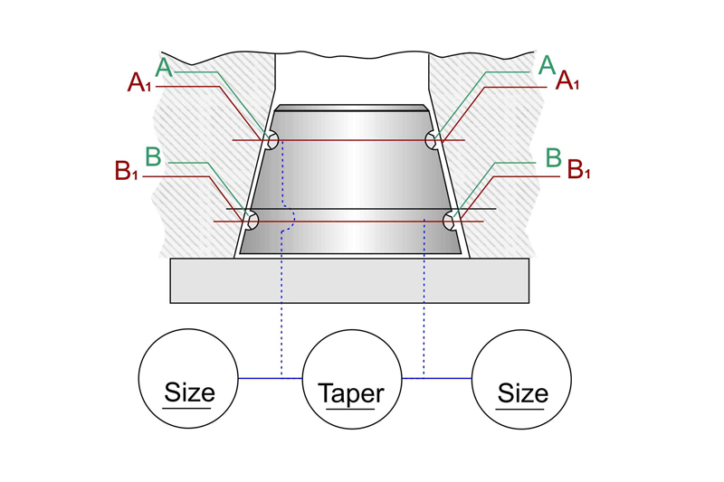
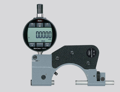
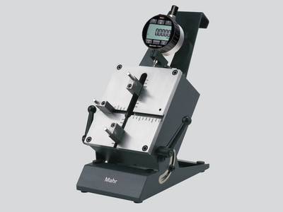
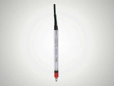
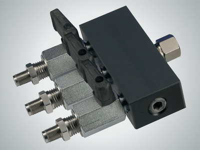
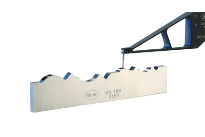
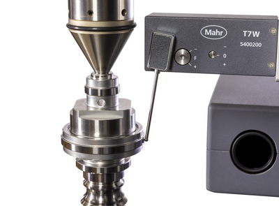
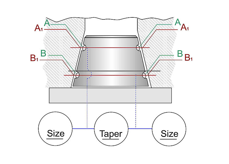
With the typical taper gage, whether it's a “jam” style that measures only taper or a clearance style that measures two diameters and taper, the two pairs of jets are set to two different heights on the taper (see Figure 1). The gage reflects a differential change between two diameters at a fixed distance along the part.
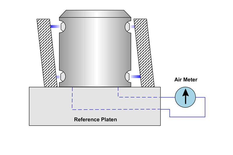
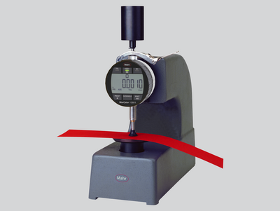
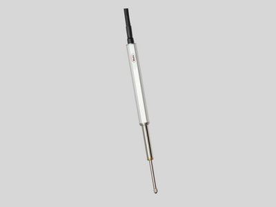
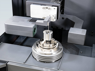
With a squareness (perpendicularity) gage, jet spacing is similar but the circuit created to combine the jets is different (see Figure 2). Top and bottom jets on each side of the air plug are channeled to opposite sides of a special air meter to provide a differential type measurement. Lack of squareness is indicated by movement of the meter hand as the part is rotated on a reference platen. This method is used primarily when the squareness reading should not be influenced by any taper condition.
The limitations of these measurements stem from jet placement. With good machining, air jets can be put very close together. In fact, it is not unusual to see jet spacing as close as .20” between the center lines of the jets—that is a great feature of air gage tooling. But think about how this affects part tolerances.
Let’s say that the specified tolerance for taper is +0.001"/-0.000” per foot. This 0.001"/ft. tolerance seems easy enough to achieve until you look at the complexity of the inspection process. First, most parts we see are much shorter than one foot, so most air gages actually compare diameters that are just 3" or 4" apart. This is no problem. But if you want to measure this taper tolerance over a very short distance, there can be issues.
Using the example above where we have a 0.20” jet spacing, the part has to meet a gaged tolerance of 0.001" ÷ 60, or 0.000016". Most common air gaging resolves to 10 µin and even high magnification air gaging only safely resolves to 5 µin—this does not leave much room for any part, gage, environment, operator, or master variation.
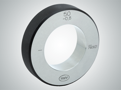
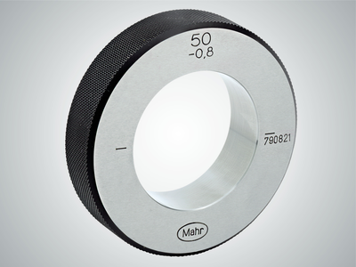
Now think about the master for the gage. Masters like to be at least five to ten times better than the system they are being used on. Or think about the gages required to measure these masters: there are enough zeros in these numbers to make the national debt envious!
Beyond that, there is the concept of trying to achieve a 10% GR&R. As this is about 4% of part tolerance, or 0.64 µin, it is just plain unattainable.
Perpendicularity gaging works in a very similar way. It is often specified over an entire length of the surface being measured and is subject to the same ratio reduction as the angular reading seen in the taper check.
So how does one achieve these measurements with certainty on the shop floor? With tighter tolerances, the old 10:1 rule for gaging is out the window. Achieving 5:1 may also be a stretch. At some point, some gaging just may not be capable of these tight tolerances over such a short area. Is it gaging at this point, or just an indication of what is happening? In some cases, an indication of what is happening is all that can be expected.