


The rule says that the gage should perform to a level better than 10% of the tolerance. While this rule has mostly been replaced by the more scientific and standardized GR&R performance test, other rules of thumb are still in play.
Gage Design
For example, we gage builders take this ten-to-one rule a little further. In order to build a gage that performs better than 10% of the tolerance in use, we need to design a gage that performs to 4% of the tolerance with the things we can control: namely the gage components and the master. That's pretty demanding but has a foundation in logic.
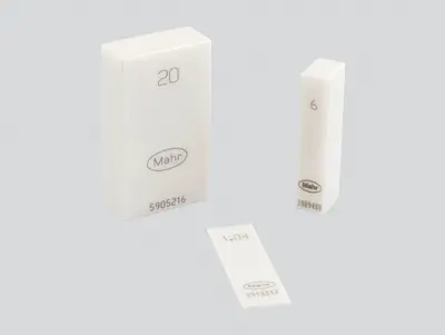
That logic comes from our SWIPE principle where the measurement process has five parts: the Standard (master), the Workpiece, the Instrument (gage), the People and the Environment. So, the two things that we have a chance of controlling are the Master and the Instrument, or two out of the five parts of the process. If we can control those two items to achieve 4%-part tolerance performance, we will achieve the 10% measuring process performance. This is where we start when trying to solve a customer's application.
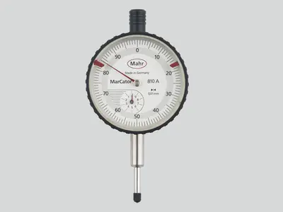
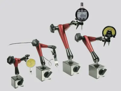
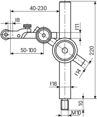
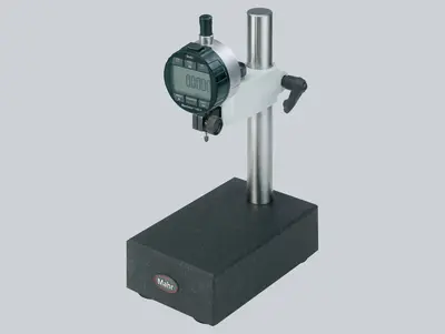
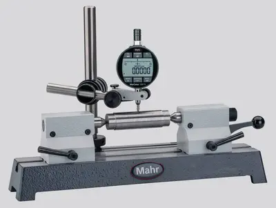
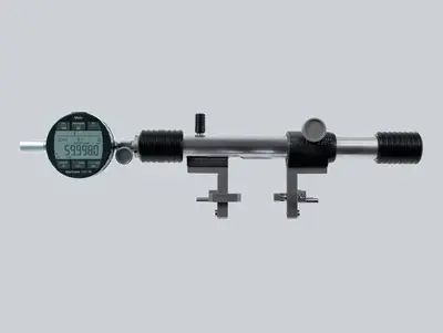
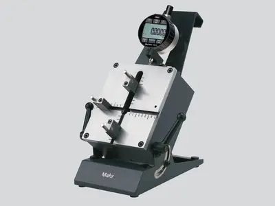
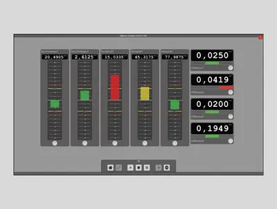
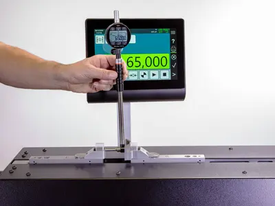
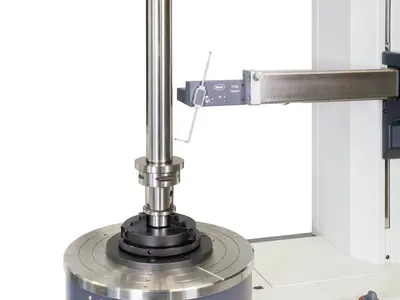
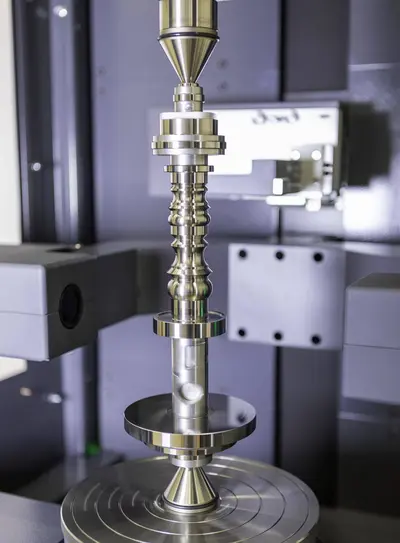
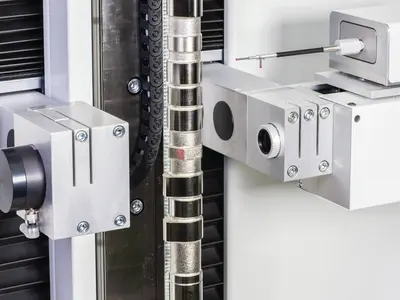
Part staging establishes the basic relationship between the measuring instrument (typically a dial or digital indicator) and the workpiece. Any error in the fixture inevitably shows up in the measurements. Many fixtures are designed around a C-frame shape and, as such, have a substantial cantilever that is subject to deflection. This problem is greatly reduced if the fixture is a solid one-piece unit.
Most fixtures also consist of a minimum of three pieces: a base, a post, and an arm. These components must be fastened together with absolutely no play between them, as any movement will be magnified at least tenfold at the workpiece. Play of only a few millionths in a couple of joints can easily accumulate so that measurements to ten-thousandths become unreliable, regardless of the level of discrimination of the instrument. Thus, in designing gage structure, the simplest is often the best.
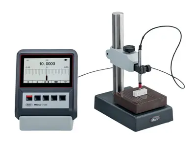
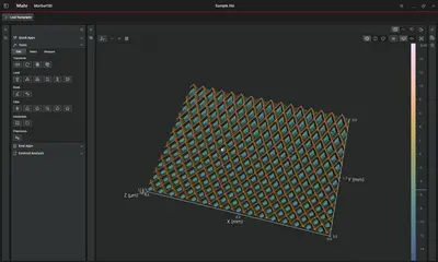
Surface Parameter Conversion
In today's global economy, machined parts are being made and shipped around the world. As a result, manufacturing and quality control engineers are often forced to decide whether or not to accept a part when the print requirements are not consistent with measurement results of the surface gages at the local facility. Some quality control engineers simply assume that if a part is checked and passed using the local parameter available, the part will also pass other checks. This assumes a constant correlation, or ratio, exists between different parameters.
Which is true, to a point: there are rules of thumb that can be used to convert Ra to Rz or Rz to Ra. Using a ratio range for Rz to Ra between 4-to-1 and 7-to-1 is a safe conversion. However, if the manufacturer uses Ra but the customer uses Rz, then the conversion ratio would be much higher, possibly as high as 20-to-1. Also, the actual shape of the part's profile will have a significant impact on these ratios.
Communication at the outset of the project can avoid most surprises. Approximate, and sometimes questionable comparisons can be avoided by developing an understanding of exactly what a parameter on a print means, and how the various parties involved in the production plan to check surface texture.
Air Versus Contact Gaging
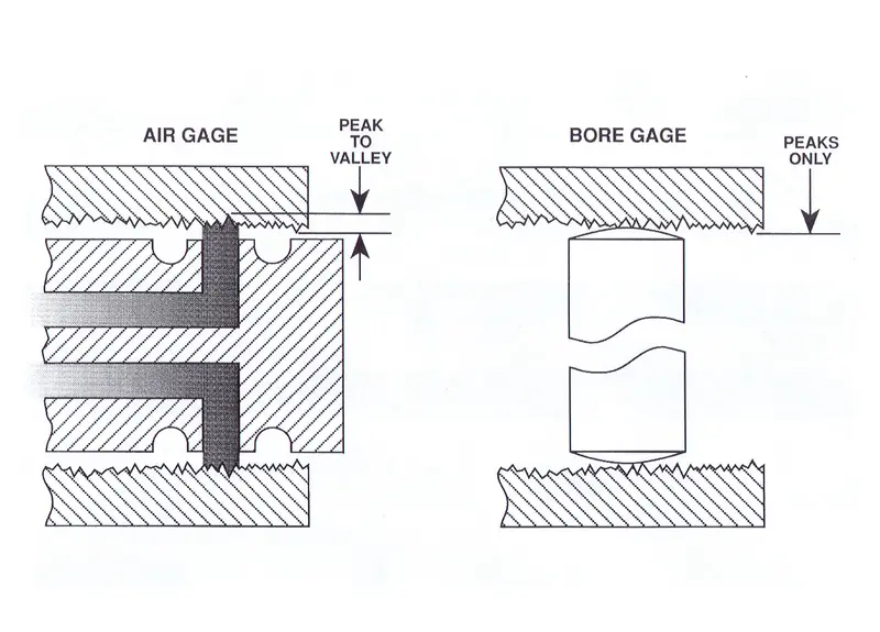
The response of air to surface finish, however, is more complicated. Think of a jet of air. The measurement 'point' is really the average area of the surface the jet is covering. Now consider the finish, or roughness, of that surface. The measurement point of the air jet is actually the average of the peaks and valleys the jet is exposed to. This is not the same measurement you would have if a contact type probe was used. This difference is a source of real gaging error, one that is most often apparent when two different inspection processes are used.
For example, let's say we have a surface finish of 100 µin. on a part, and we're measuring with an air gage comparator and two-jet air plug that has a range typically used to measure a 0.003 in. tolerance. The typical gaging rule of thumb says you should have no sources of error greater than 10% of the tolerance. In this example, that's 0.0003 in. If we used this plug on the 100 µin. surface, the average measuring line would actually be 50 µin. below the peak line. Double this error for the two jets and you get 0.0001 in., or 30% of the allowable error. That's pretty significant and air would probably not be a good choice for this part. As a general rule, the limit for surface finish with an air gage is about 60 µin., but it really depends on the part tolerance.
The measurement point of an air jet is actually the average of the peaks and valleys the jet is exposed to. This is not the same measurement you would have if a contact type probe was used. This difference is a source of real gaging error, one that is most often apparent when two different inspection processes are used.