


We have discussed in past articles the pros and cons of doing gage calibrations internally or by an external calibration facility. Both have their cost and advantages/disadvantages. However, calipers are measuring instruments with fairly loose performance tolerances and may be a candidate for doing in-house calibrations if you have the tools and facilities in place.
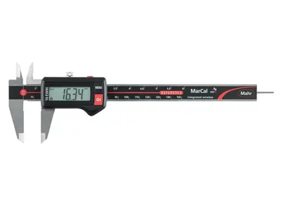
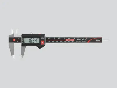
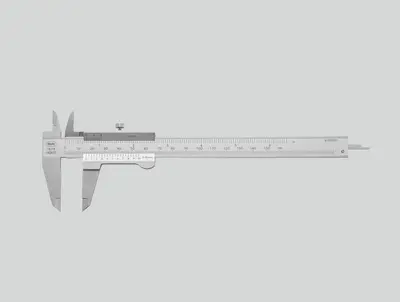
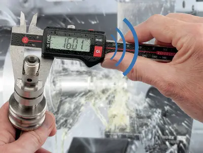
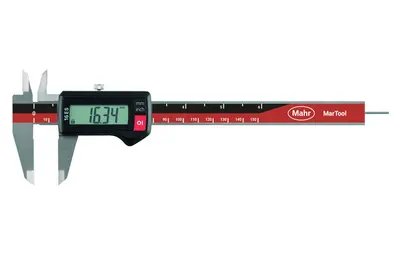
The following information covers digital calipers but can also be used for dial or even Vernier calipers (if those are still in use). Since most calipers have not only OD jaws, we can also check the tools’ ID jaws and depth-measuring rod should it have one. Running though a calibration process for a caliper involves comparing its readings to numerous standards over its measuring range, the most common being 6”/150mm. However, with the right standards, any length caliper can be checked.
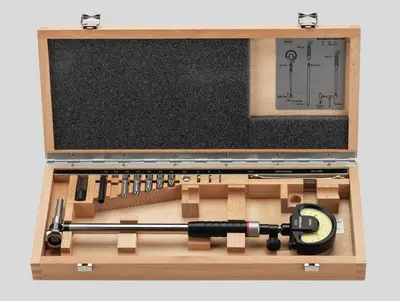
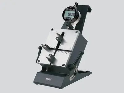
Since a caliper is a length-measuring device, gageblocks are the go to standard but there are special kits available that provide different versions of length standards for checking the caliper. When checking any measuring device it is obvious to check the full range of the instrument, say 25%, 50% 75% and 100% of the measuring range. But for versions of the tool that have a short-range indicator, such as a dial caliper, you probably want to make some short-range checks that cover the range of the indicator face.
The tools needed to do a caliper calibration include:
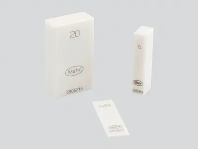
- Gageblocks with accessories or other length standards specifically designed for calipers. Of course, they need to be under control themselves with a current calibration certification
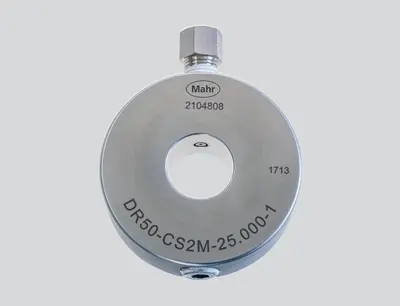
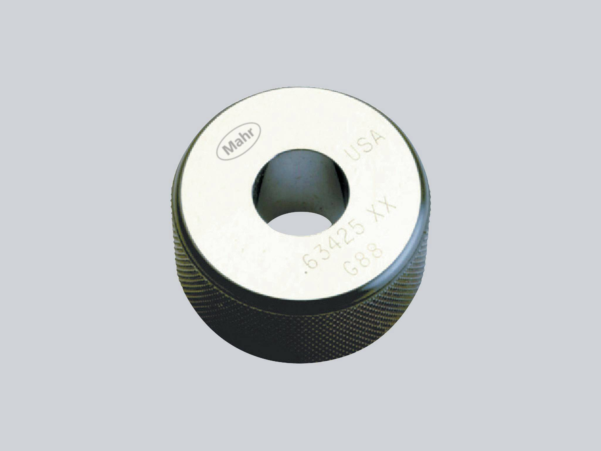
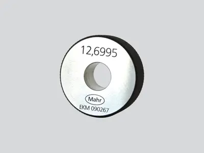
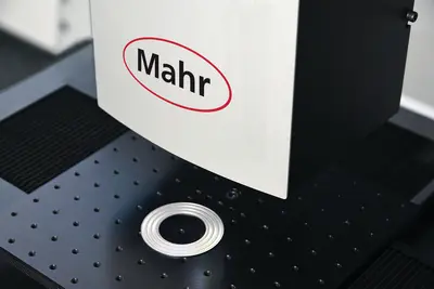
- A ring gage to check the condition of the ID jaws or a set of rings to check the performance of the ID jaws over the measuring range
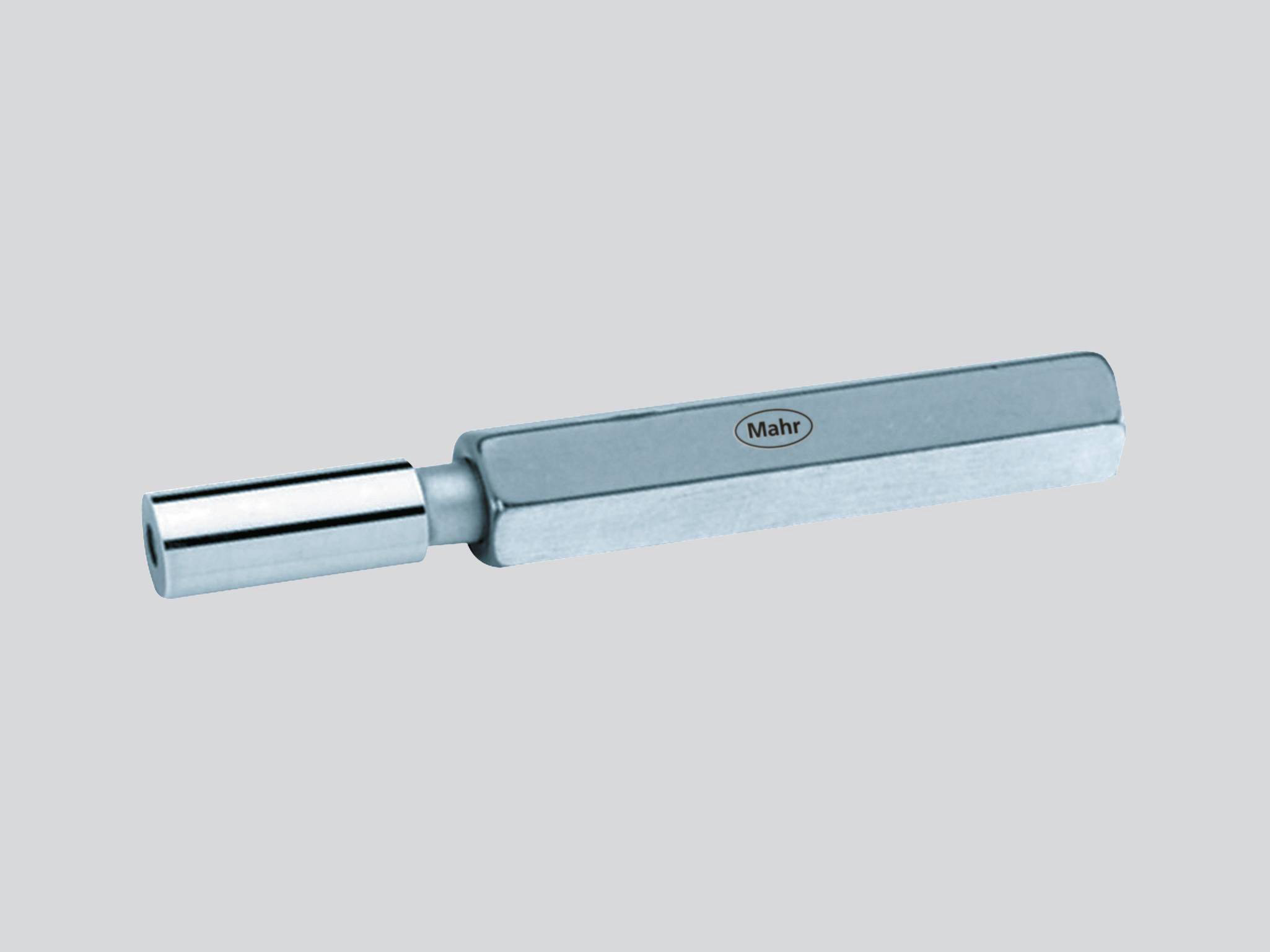
- A gage pin to check the inside diameter jaws for parallelism
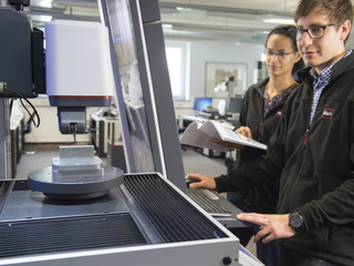
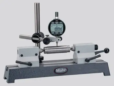
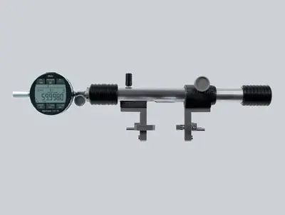
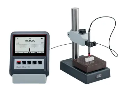
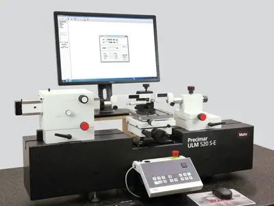
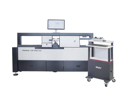
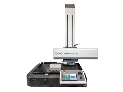
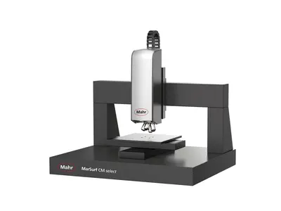
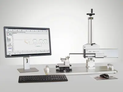
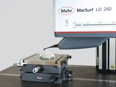
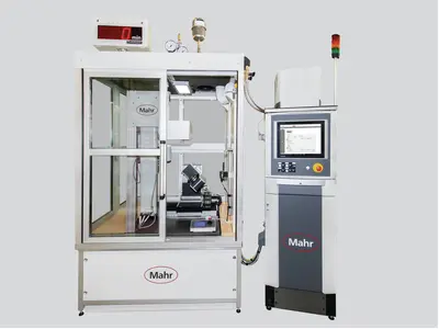
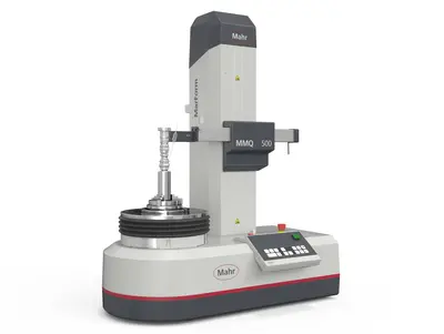
- If you have the luxury of a universal length measuring machine, there are accessories available to help calibrate calipers
Next, it comes down to determining a procedure, thinking about sources of errors to establish an uncertainty budget and finding ways to reduce these errors to obtain a budget that meets the calibration requirements.
The procedure includes:
- The list of tools required to begin the calibration
- Defining the process for doing the calibration procedure, such as:
- Clean the jaws (ID and OD), rack and depth rod of the caliper
- Clean gageblocks, master ring and pin gage
- Zero and rezero the caliper to set zero and check repeat
- Check parallelism of the OD jaws with the pin gage
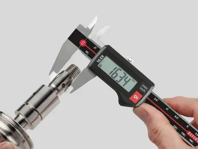
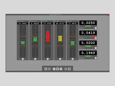
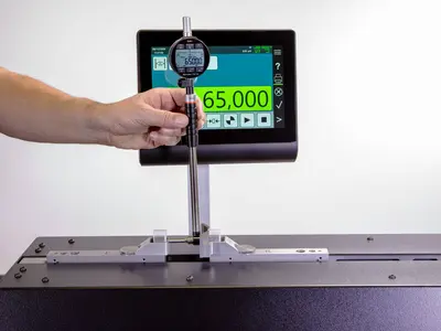
- Check and record the calibration reading of the caliper against the gageblocks
- Check and record the calibration reading of the caliper against the master rings
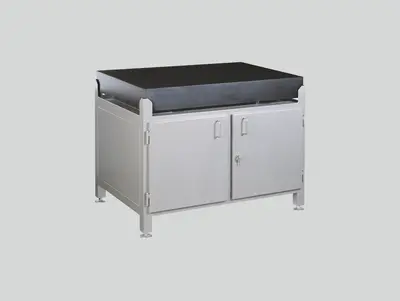
- Check and record the calibration reading of the depth rod against a gageblock on a surface plate
- Compare all readings against the tolerances set for the caliper
The resulting information can be stored in a calibration document that contains all the information required by your policy to verify the performance of the caliper, information about the caliper itself, who performed the check, the condition under which the checks were made, the traceability of the standards and the uncertainty budget established.
Some of the typical errors one might see in establishing the uncertainty budget may include the uncertainty of the standards, human errors such inconsistent measuring force, environmental conditions, dirt, temperature and vibration and influences from the caliper itself such as wear.
To minimize these sources of errors, one can take care during the set-up of the process to:
- Inspect the caliper well to ensure it is clean, and has no nicks or burrs or other foreign material
- Ensure the tool is not bent or bowed
- Wear gloves to reduce heat and dirt contamination
- Take readings at various places on the jaw at each calibration point, looking for variations
- Recheck zero often
- Orient the gageblocks consistently
- Ensure that a locking mechanism is loose and the tool moves freely
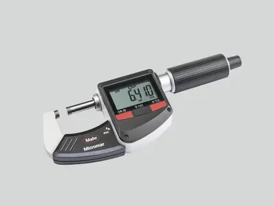
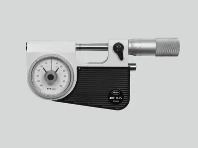
A lot of this process is similar to the calibration process for micrometers, depth gages and other mechanical gage tools. Knowing the process, your capabilities and being able to quantify them is what is most important. If you can do this, then you may be able to start small with doing some basic calibrations on your own.